


Installation
2-153000-A2-GB41-40 May 1998
Installing an SDCP
If you want to mount an SDCP and the SDCP ribbon
cable is not installed, remove the CO Power Unit from the
carrier and follow the instructions in the SDCP Ribbon
Cable Installation section in the COMSPHERE
3000 Series Carrier Installation Manual.
NOTE
This procedure is only used
when installing an SDCP onto a
carrier operating with a CO
Power Unit. All other carriers
use the standard SDCP
installation procedure as
described in the Shared
Diagnostic Control Panel
(SDCP) Installation section in
the
COMSPHERE 3000 Series
Carrier Installation Manual.
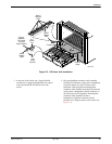
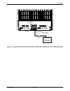
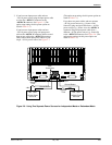
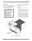
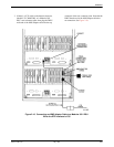
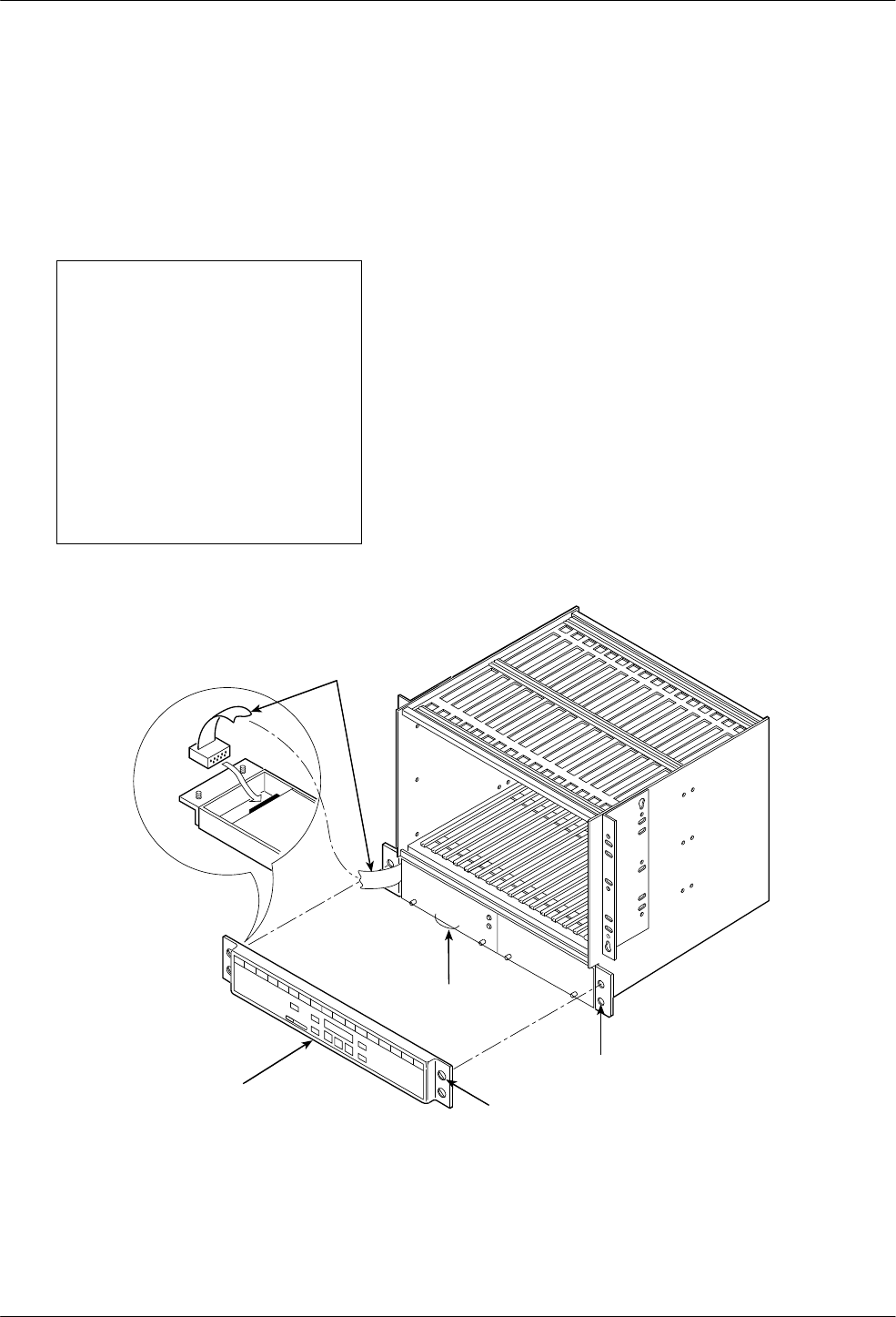
If you want to mount a shared Diagnostic Control
Panel (SDCP) on the carrier and the SDCP ribbon cable is
installed (refer to Figure 2-8):
" Procedure
1. Raise the carrier 1.5 inches above the carrier
below it.
(In a Paradyne COMSPHERE 72-inch cabinet
(4000-B2-201), if you mount an SDCP onto a
carrier operating with a CO Power Unit, then only
five carriers can be installed in the cabinet instead
of the usual six.)
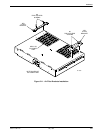
2. Remove the power module (the left power module
if there are two power modules in the CO Power
Unit) by loosening the two captive screws on the
front of the power module. Hold onto the power
module handle and slide the power module out.
Then, remove the handle on the power module by
using a small Phillips-head screwdriver to loosen
the screws behind the power module’s faceplate.
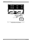
497-13757-02
SDCP
RIBBON
CABLE
NYLON
CABLE
TIE
BOTTOM
SCREW HOLE
TOP
CAPTIVE
SCREW
SHARED DIAGNOSTIC
CONTROL PANEL
(SDCP)
Figure 2-8. Installing the SDCP