


26
97-15526
50
1
25
10
8546-A2-GN10-20
October 1997
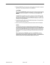
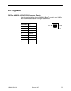
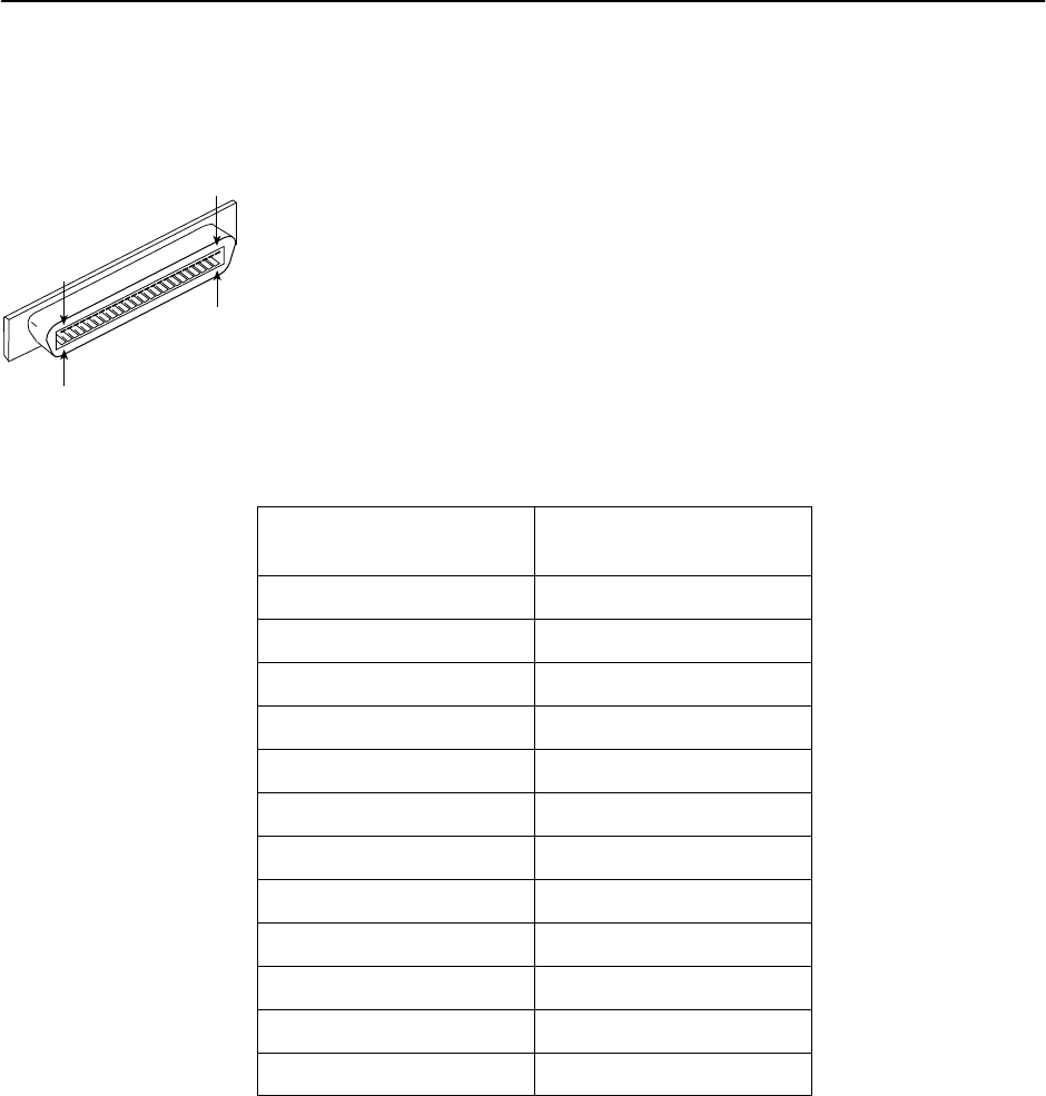
HotWire 8600 DSLAM Telco 50-pin Connector Pinouts for DSL Loops
and POTS Splitters
The Telco 50-pin receptacle on the front panel provides the two-wire loop
interface from each 8546 DSL port to either the POTS Splitter shelf or, if the
loop is not being shared with POTS, then to the MDF. The following table lists
the pin assignments for each of these interfaces.
NOTE:
When the 8600 chassis is the base chassis, the MCC is installed in Slot 1
and the Tip and Ring wiring for Slot 1 is not active.
Also, pins 13 through 25 and 38 through 50 of all HotWire 8600 chassis
are not used.
CONNECTOR
(8546 DSL Slot, Port #)
CONNECTOR PINS
(Tip, Ring)
Slot 1, Port 1 1, 26
Slot 1, Port 2 2, 27
Slot 1, Port 3 3, 28
Slot 1, Port 4 4, 29
Slot 2, Port 1 5, 30
Slot 2, Port 2 6, 31
Slot 2, Port 3 7, 32
Slot 2, Port 4 8, 33
Slot 3, Port 1 9, 34
Slot 3, Port 2 10, 35
Slot 3, Port 3 11, 36
Slot 3, Port 4 12, 37