


8
8546-A2-GN10-20
October 1997
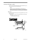
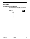
Connecting the DSL Cards to the Ethernet Hubs or Switches
"
Procedure
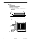
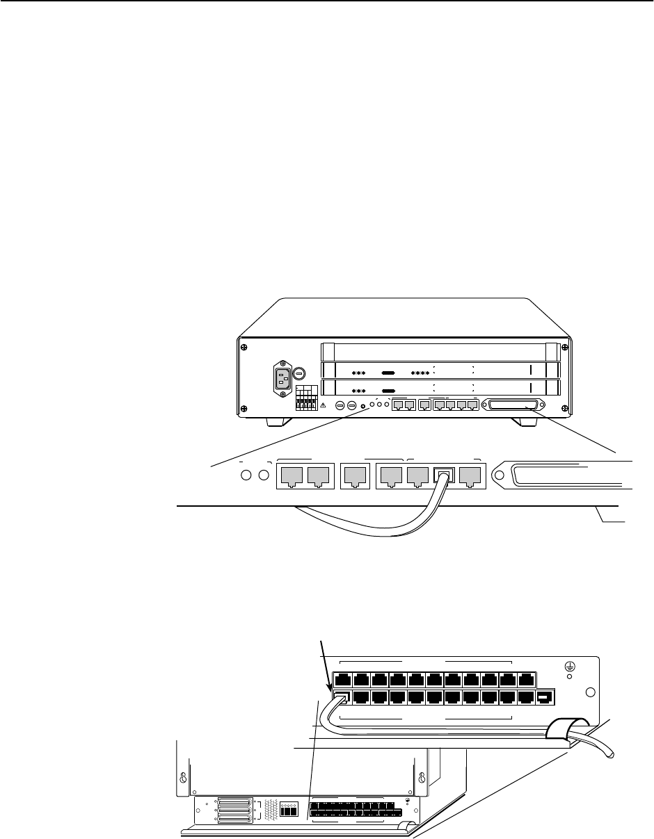
To connect the 8546 DSL cards to the Ethernet hubs or switches:
1. Plug the end of an 8-pin modular cable into the appropriate LAN/WAN SLOT
port of the chassis. For example, if you want to connect to the LAN/WAN port
of an 8546 DSL card, insert the 8-pin modular cable in LAN/WAN Slot #2.
2. Plug the other end of the cable into your Ethernet hub or switch connector.
Refer to
Pin Assignments
on page 9 for pin assignments.
— On a HotWire 8600 DSLAM chassis:
97-15375-01
LAN/WAN SLOT
2
A
IN
B
DC PWR
OUT SERIAL
MCC 1
MANAGEMENT
3
A
AC
INPUT
AC
48VDC CLASS 2 OR
LIMITED PWR SOURCE
RTN48V
AAB B
T5A
250A
LAN/WAN SLOT
2
46
B
.
.
.
3
.
1
2
POSITION
STACK
ALM
A
IN
B
DC FUSES
T4A, MIN. 48V
5
DC PWR
FAN
OUT SERIAL
MCC 1
MANAGEMENT
3
LINE
1
2
3
SYSTEM
OK
Alrm
Test
TX
RX
Col
ETHERNET
MCC
8000
SYSTEM
OK
Alrm
Test
TX
RX
Col
1
2
3
4
ETHERNET
DSL PORT
RADSL
8546
SYSTEM
OK
Alrm
Test
TX
RX
Col
1
2
3
4
ETHERNET
DSL PORT
RADSL
8546
To Hub Connector
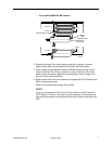
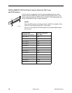
— On a HotWire 8800 DSLAM chassis:
MGT
SERIAL
MGT
10BT
ALARM
SLOTS 1 - 6
SLOTS 7-12
SLOTS 13-18
LINES
A
B
-48V (A)
-48V INPUT
-48V (B)
RET (A)
RET (B)
FR GND
2
4
6
8
10
12
14
16
18
19
1
35
7
9
11
13 15
17
LAN/WAN SLOT
20
LAN/WAN SLOT
MGT
SERIAL
MGT
10BT
ALARM
2
4
6
8
10
12
14
16
18
19
1
35
7
9
11
13 15
17
LAN/WAN SLOT
20
LAN/WAN SLOT
LAN/WAN SLOT
PORT 1
97-15385