


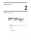
2. Menus and Screens
8335-A2-GB20-70 February 2003 2-7
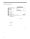
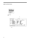
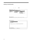
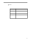
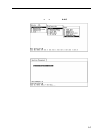
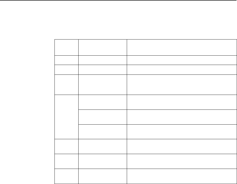
The following information is displayed on the Quick Card Select screen.
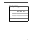
Table 2-3. Quick Card Select Screen
Column
Heading Display Description
Slot <slot number> Slot number of card in chassis.
Card <model number> Model number of card.
Type <card type(ports)> Card type followed, if appropriate, by the number of
ports it supports. For example, SCM, SDSL(16),
Reach(24), ADSL(12),or SHDSL(24).
Status Position 1: T or _ Test mode. Card currently in test mode or _ for no
active test.
Position 2: M or _ Major alarm. Major alarm present on card or _ for no
active major alarm.
Position 3: R or _ Minor alarm. Minor alarm present on card or _ for no
minor alarm active.
UpLinks <uplink status> Status of uplink:
U=Up, D=Down, X=Disabled, A=Alarm
ATM <ATM uplink status> Status of ATM uplink:
U=Up, D=Down, X=Disabled, A=Alarm
Links <dsllink status> Status of DSL ports:
U=Up, D=Down, X=Disabled, A=Alarm, E=Empty slot