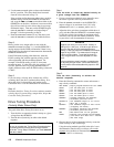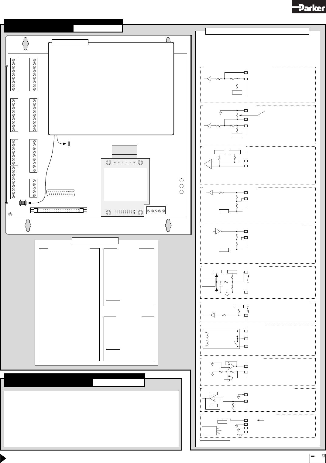
• STATUS LED: Green = 5VDC power is applied. Red = power reset required. Off = no power.
DSBL (axis disabled) LEDs: Off = O.K. On = drive is disabled (see page 28 for possible causes).
• Status information (see command descriptions in
6000 Series Software Reference
):
General status information.....................TASF, TSSF, TSTAT
Limits (end-of-travel, home)...................TASF, TLIM
ENBL input.............................................TINOF (bit #6)
Programmable inputs and TRG-n...........TIN, INFNC
Programmable outputs...........................TOUT, OUTFNC
• ENBL input must be grounded to GND terminal to allow motion.
• NEG & POS inputs must be grounded to GND terminal to allow motion (or disable with LHØ command).
• To help prevent electrical noise, shield all connections at one end only (see also Appendix B).
• Error messages while programming or executing programs – see
6000 Series Programmer's Guide
.
• Technical support – see phone numbers on inside of front cover, and the HELP command response.
AUX-P (Inputs are pulled up to 5V
via
R45; alternative is to remove R45 and
connect AUX-P to an external 5-24VDC
supply. To sink current, remove R45
and connect AUX-P to GND terminal.)
Limits and Trigger Inputs (pg 12 & 15)
–
+
A–, B–, or Z–
A+, B+, or Z+
Encoder Inputs (pg 13)
General-Purpose Programmable Input
IN-P (Inputs are pulled up to 5V via R12;
alternative is to remove R12 and
connect IN-P to an external supply of up
to 24VDC. To sink current, remove R12
and connect IN-P to a GND terminal.)
Specs: HCMOS-compatible*; voltage range = 0-24VDC.
Programmable Inputs (pg 16)
General-Purpose Programmable
Output
OUT-P (Outputs are pulled up to 5V via
R13; alternative is to remove R13 &
connect OUT-P to an external supply of
up to 24VDC)
Specs: Open collector output. Max. voltage in OFF state (not sinking
current) = 24V; Max. current in ON state (sinking) = 30mA.
Programmable Outputs, includes OUT-A & OUT-B (pg 16)
DC Input............5VDC ±5%, 4A min. (current requirements depend on
.....................the type and amount of I/O used – see page 20).
Serial Com.........RS-232C 3-wire (Rx, Tx & GND on AUX connector);
.....................Up to 99 units in a daisy chain.
.....................9600 baud (or use AutoBaud feature – see page 6);
.....................8 data bits; 1 stop bit; no parity.
* HCMOS-compatible levels: Low
≤
1.00V, High
≥
3.25V.
Connections
Troubleshooting
I/O SPECIFICATIONS & INTERNAL SCHEMATICS
Specs: Differential comparator. Use 2-phase quadrature encoders;
max. frequency = 1.6 MHz; min. time between transitions = 625 ns.
TTL levels (Low ≤ 0.4V, High ≥ 2.4V); range = 0-5VDC.
+1.8VDC+5VDC
22 KΩ 22 KΩ
6
.8 KΩ
47 KΩ
74HCxx
7406
(open collector)
4
.7 KΩ
See also pages 5-23
See also pages 28-31
OEM6250 2-Axis Servo Controller
We welcome your feedback on our products and user guides. Please send your responses to our email address: 6000user@cmotor.com
Direct
y
our technical
q
uestions to
y
our local ATC or distributor
,
or to the numbers printed on the inside front cover of this document.
Automation
email
150 KΩ
49.9 KΩ
0
.1 µF
10.0 KΩ
35 V
35 V
8 Channel
8-bit A/D
Converter
GND
Specs: Voltage range = 0-2.5VDC, 8-bit.
Must not exceed 5VDC.
Analog Channel Inputs (pins 1-3)
Ground (pin 14)
DFT; and Axes Select, Velocity, Release,
Trigger, & Aux (JOYSTICK pins 15-19)
6.8 KΩ
74HCxx
47 KΩ
+5VDC
Specs: HCMOS-compatible*;
voltage range = 0-24VDC.
+5VDC
+5VDC
Drive Fault Inputs (pg 7) and Joystick Digital Inputs (pg 14)
OTHER PIN OUTS
Pin Function
1 Input #16
(MSB of inputs)
3 Input #15
5 Input #14
7 Input #13
9 Input #12
11 Input #11
13 Input #10
15 Input #9
17 Output #8 (MSB of outputs)
19 Output #7
21 Output #6
23 Output #5
25 Input #8
27 Input #7
29 Input #6
31 Input #5
33 Output #4
35 Output #3
37 Output #2
39 Output #1 (LSB of outputs)
41 Input #4
43 Input #3
45 Input #2
47 Input #1 (LSB of inputs)
49 +5VDC
Even pins connected to common logic gnd.
MSB = most significant bit.
LSB = least significant bit.
PROGRAMMABLE I/O
Pin Function
1 Analog Channel #1
2 Analog Channel #2
3 Analog Channel #3
8 Shield (chassis gnd)
14 Digital Ground
15 Axes Select Input
16 Velocity Select Input
17 Release Input
18 Trigger Input
19 Auxiliary Input
23 +5VDC Output
JOYSTICK
Pins 4-7, 9-13, 20-21, 24-25 are reserved
6.8 KΩ
74HCxx
47 KΩ
Specs: HCMOS-compatible*; voltage range = 0-24VDC.
Remove R25 before
connecting your ENBL switch.
R12 (0 Ω)
R13 (0 Ω)
+5VDC
+5VDC
LIMITSAUX
JOYSTICK
RP240
PROGRAMMABLE INPUT/OUTPUT
15
POWER
+15V NC-15V GND +5V
1
9
1
9
1
7
5
1
9
1
1
2
49
50
13 1
25 14
SHLD
COM
SHTNC
SHTNO
DFT
AGND
RSVD
CMD-
CMD+
SHLD
COM
SHTNC
SHTNO
DFT
AGND
RSVD
CMD-
CMD+
Rx
Tx
GND
SHLD
+5V
OUT-P
IN-P
TRG-A
TRG-B
GND
OUT-A
OUT-B
GND
ENBL
+5V
AUX-P
1POS
1NEG
1HOM
GND
2POS
2NEG
2HOM
GND
SHLD
SHLD
Tx
Rx
GND
+5V
TH1
DRIVE 2
DRIVE 1
1
9
9
1
9
1
+5V
A+
A-
B+
B-
Z+
Z-
GND
SHLD
+5V
A+
A-
B+
B-
Z+
Z-
GND
SHLD
ENCODER 2
ENCODER 1
DSBL2 DSBL1 STATUS
DIMENSIONS & MOUNTING: refer to page 4.
Pin Function
1 Analog input #1
2 Analog input #2
3 Analog Ground
4
not connected
5
not connected
6
not connected
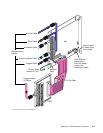
ANI BOARD
The ±10V analog inputs (ANI inputs) are
available only if you ordered the
OEM6250-ANI or OPT-OEM6250-A.
R45
R25
R12
R13
Resistor R12. R12 pulls up all 16 programmable inputs to the internal
+5VDC supply. You must remove R12 before you can use the IN-P pullup
terminal for the programmable inputs. To pull up the programmable inputs
to a voltage other than the internal +5VDC, remove R12 and connect an
external 5-24VDC supply to the IN-P terminal. To sink current on the
programmable inputs, remove R12 and connect the IN-P to GND.
Resistor R13. R13 pulls up all 8 programmable outputs to the internal
+5VDC supply. You must remove R13 before you can use the OUT-P
pullup terminal for the programmable outputs. To pull up the
programmable inputs to a voltage other than the internal +5VDC, remove
R13 and connect an external 5-24VDC supply to the OUT-P terminal.
Resistor R25. R25 connects the enable input (ENBL) to ground, thereby
allowing motion to occur. To connect a normally-closed external switch for
operating the emergency stop function (see page 11), you must first
remove R25.
Resistor R45. R45 pulls up the enable (ENBL), trigger (TRG-A/B), and
limit (POS, NEG, HOM) inputs to the internal +5VDC supply. You must
remove R45 before you can use the AUX-P pullup terminal for these
inputs. To pull up these inputs to a voltage other than the internal +5VDC,
remove R45 and connect an external 5-24VDC supply to the AUX-P
terminal. To sink current on these inputs, remove R45 and connect AUX-P
to GND.
Zero-Ohm Resistors
6 5 4 3 2 1
ANI BOARD
If you ordered the
“OEM6250-ANI” product,
this option board is
factory installed. If you
ordered the board
separately (p/n “OPT-
OEM6250-A”), you must
install it–see page 4.
POS, NEG, HOM or TRG-n
+5VDC
R45 (0 Ω)
AUX-P (used also by DFT, POS, NEG,
HOM and TRG-n — see schematic
above)
Enable (ENBL) Input (pg 11)
6.8 KΩ
74HCxx
47 KΩ
Specs: HCMOS-compatible*; voltage range = 0-24VDC.
ENBL
+5VDC
R45 (0 Ω)
GND
Digital GND
R25 (0 Ω)
GND
+5V
SHLD
5V terminal found on multiple
connectors. Total load limit
depends on current supplied from
your external DC power supply to
the power input connector.
Terminals found on multiple connectors
Digital GND
Chassis GND
AGND
Analog Input Terminal
ANI Input, from the optional analog input card (pg 11)
AGND
COM (signal common for shutdown)
Drive Shutdown Outputs (pg 7-10)
SHTNC (normally closed)
SHTNO (normally open)
Closed if DRIVEØ
Open if DRIVE1
Open if DRIVEØ
Closed if DRIVE1
Specs: Solid state relay. Max. rating = 175VDC, 0.25A, 3W.
AGND
AGND
Command +
CMD+ (command signal output)
CMD– (command signal return)
Drive Command Output (pg 7-10)
Specs: ±10V analog output; 12-bit DAC.
Load should be > 2KΩ impedance.
150 KΩ
AGND
–15V
+15V
AGND
Analog GND
+5VDC
Specs: ±10V analog input; 14-bit ADC.
Grounding
diagram on
page 5.
Joystick Analog Inputs (pg 14)


