8
3.0 INSTALLATION
Because the Model 1058 requires no configuration, it can be installed
quickly. If you are installing a standalone unit, refer to section 3.1 “Standal-
one unit installation”. Otherwise, refer to section 3.2 “Rack card installation”.
3.1 STANDALONE UNIT INSTALLATION
Do the following:
1. Connect the line interface between the units (refer to section 3.3,
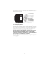
“Connecting the Twisted-Pair Line Interface” on page 10)
Note
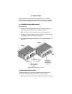
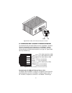
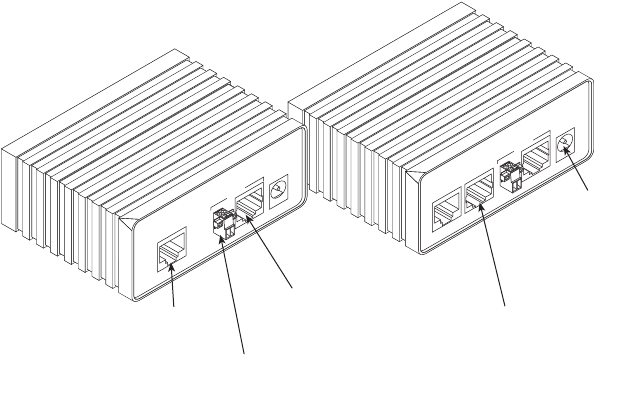
See Figure 2 for the standalone unit’s rear panel arrangements.
2. Connect the Ethernet interface (refer to section 3.4, “Connecting the
10/100Base-T Ethernet Interface” on page 11).
3. Connect the power plug (refer to section 3.6, “Connecting Power” on
page 13).
Figure 2.
Model 1058 standalone rear panel
3.2 RACK CARD INSTALLATION
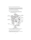
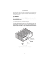
The Model 1058 rack card version comprises a front card and a rear
card.Do the following to install the cards into the rack chassis:
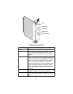
1. Slide the rear card into the back of the chassis along the metal rails.
Ethernet
VLINK
Power
Made in the USA
POTS/ISDN
twisted-pair
terminal block
interface
Power
jack
Ethernet
VLINK
Power
Made in the USA
Ethernet
port
VDSL twisted-pair
terminal block
interface
VDSL twisted-pair
RJ-45 interface
POTS/ISDN
1058DV
1058D


