


The table below provides an overview of strap functions for the DB-
25/modular cards. Following this overview is a detailed description of
each strap's function.
Line Shield & FRGND (JB2)
This strap pertains to the line interface. In the connected (closed)
position, this strap links RJ-11 pins 1 and 6, or RJ-45 pins 2 and 7 to
frame ground. These pins can be used as connections for the twisted
pair cable shield. In the open (disconnected) position, pins 1 and 6 (or
2 and 7) remain connected to each other, but are "lifted" from the frame
ground.
JB2
Position 1&2 = Line Shield and FRGND Connected
Position 2&3 = Line Shield and FRGND Not Connected
DTE Shield (Pin 1) & FRGND (JB3)
In the connected (closed) position, this strap links DB-25 pin 1 and
frame ground. In the open (disconnected) position, pin 1 is "lifted" from
frame ground.
JB3
Position 1&2 = DTE Shield (Pin 1) and FRGND Connected
Position 2&3 = DTE Shield (Pin 1) and FRGND Not Connected
SGND & FRGND (JB4)
In the connected (closed) position, this strap links DB-25 pin 7
(Signal Ground) and frame ground. In the open (disconnected)
position, pin 1 is "lifted" from frame ground.
JB4
Position 1&2 = SGND (pin 7) and FRGND Connected
Position 2&3 = SGND (Pin 7) and FRGND Not Connected
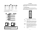
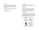
3.4.2 RJ-45/RJ-11 & RJ-45/RJ-45 Strap Settings
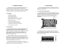
Figure 8 (opposite page) shows strap locations for the Model
1000RCM1D11 (RJ-45/RJ-11) and the Model 1000RCM1D45 (RJ-45/
RJ-45) rear cards. These straps determine various grounding
characteristics for the RS-232 and twisted pair lines.
The table below provides an overview of strap functions for the
modular/modular cards. Following the table is a detailed description of
each strap's function.
Line Shield & FRGND (JB2)
This strap pertains to the line interface. In the connected (closed)
position, this strap links RJ-11 pins 1 and 6, or RJ-45 pins 2 and 7 to
frame ground. These pins can be used as connections for the twisted
pair cable shield. In the open (disconnected) position, pins 1 and 6 (or
2 and 7) remain connected to each other, but are "lifted" from frame
ground.
JB2
Position 1&2 = Line Shield and FRGND Connected
Position 2&3 = Line Shield and FRGND Not Connected
9 10
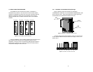
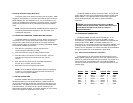
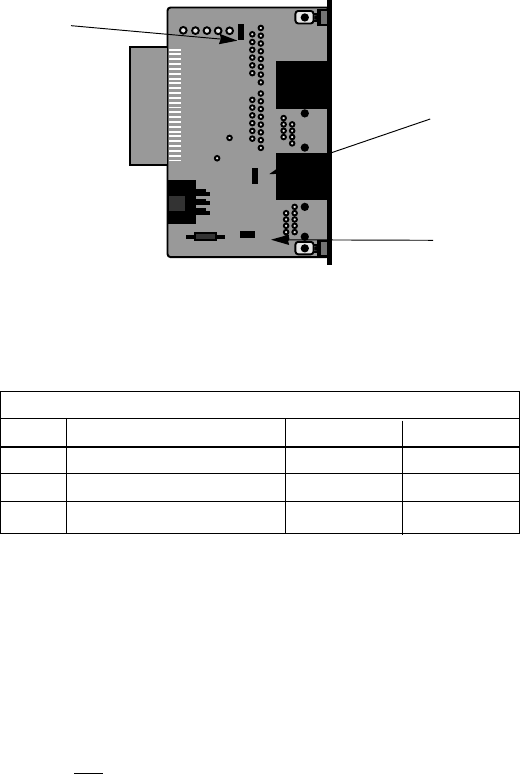
INTERFACE CARD STRAP SUMMARY TABLE #2
Strap Function Position 1&2 Position 2&3
JB2 Line Shield & FRGND Connected Open*
JB5 SGND & FRGND Connected Open*
JB6 DTE Pin 2 DSR* RI
* indicates factory default
Figure 8. RJ-45/RJ-11 & RJ-45/RJ-45 strap locations
JB2
(peg 1 on top)
JB6
(peg 1 on top)
JB5
(peg 1 on left)
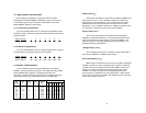
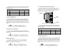
INTERFACE CARD STRAP SUMMARY TABLE #1
Strap Function Position 1&2 Position 2&3
JB2 Line Shield & FRGND Connected Open*
JB3 DTE Shield (Pin1) & FRGND Connected Open*
JB4 FRGND & SGND Connected Open*
* indicates factory default