3.4 REAR CARD CONFIGURATION
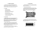
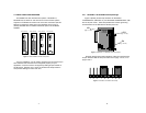
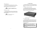
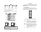
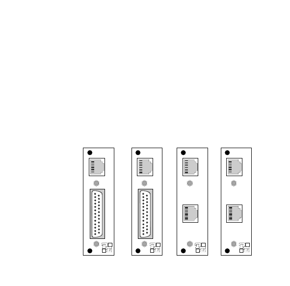
The 1060RC has four interface card options: DB-25/RJ-11,
DB-25/RJ-45, RJ-45/RJ-11 and dual RJ-45. Each of these options
supports one RS-232 connection and one 4-wire connection (the RS-
232 port is always the
lower
port on the interface card). Figure 4
(below) illustrates the four different interface options for the Model
1060RC:
Prior to installation, you will need to examine the rear card that you
have selected and ensure that it is configured properly for your
application. Each rear card is configured by setting straps located on
the PC board. Sections 3.4.1 and 3.4.2 describe the strap locations
and possible settings for each rear card.
3.4.1 DB-25/RJ-11 & DB-25/RJ-45 Strap Settings
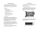
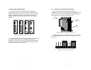
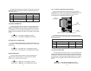
Figure 5 (below) shows strap locations for the Model
1000RCM12511 (DB-25/RJ-11) and the Model 1000RCM12545 (DB-
25/ RJ-45) rear cards. These straps determine various grounding
characteristics for the RS-232 and twisted pair lines.
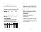
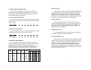
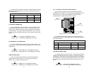
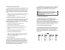
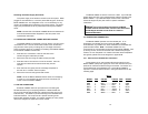
Figure 6 (below) shows the orientation of the rear interface card
straps. Observe that the strap can either be on pegs 1 and 2, or on
pegs 2 and 3.
87
Figure 6. Orientation of interface card straps
123 123 123
JB2
(peg 1 on left)
JB3
(peg 1 on top)
JB4
(peg 1 on left)
Figure 4. Model 1060RC interface card options
RJ-11 (6-wire)
RJ-45 (8-wire) RJ-45 (8-wire) RJ-11 (6-wire)
DB-25 F
DB-25 F RJ-45 (10-wIre) RJ-45 (10-wire)
Figure 5. DB-25/RJ-11 & DB-25/RJ-45 strap locations


