


Control Input (C
in
):
The Control Input signal is used by the local Model 1060RC as an
input signal to “turn on” (in the “Enabled” settings) and allow data
transmission to the remote device. This is required for half-duplex/
switched-carrier environments as well as in hardware flow control
applications. In the “Disabled” settings, the 1060RC is always “turned
on” and sends a continuous carrier to the remote 1060RC.
Control Output (C
out
):
The Control Output signal is transmitted by the local Model
1060RC to its attached DTE device. This signal should be the same
logic state as the Control Input signal on the remote 1060RC. This
signal is required in half-duplex/switched carrier environments or in
hardware flow control applications.
+Voltage Output (+V
out
):
The +Voltage Output signal is a constant positive voltage that is
sent from the 1060RC to its attached DTE device.
Carrier Controlled by (C
in
):
When Carrier Controlled by Control Input is “Enabled”, the Model
1060RC is “turned on” by the corresponding C
in
Signal from the DTE.
In effect, the Control Input signal on the local 1060RC "controls" the
presence of "carrier" and the Control Output signal on the remote
1060RC. This setting is required in half-duplex/switched carrier
environments or in hardware flow control applications. When Carrier
Control by Control Input is “Disabled”, the 1060RC sends a continuous
carrier and is always “turned on”.
6
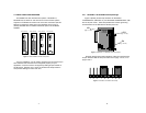
3.2 "QUICK SET-UP" INSTRUCTIONS
In the majority of applications, you will not need an in-depth
knowledge of the Model 1060RC's capabilities to get up and running.
The following "quick set-up" DIP switch configurations cover most
Model 1060RC operating environments.
3.2.1 Point-to-Point Applications
If you are installing these units in a point-to-point application with a
computer, printer or terminal, configure the DIP switches on both Model
1060s as follows:
Switch
Number: 1 2 3 4 5 6 7
Positions ON ON ON OFF OFF OFF OFF
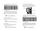
3.2.2 Multi-Point Applications
If you are installing these units in a multipoint application, configure
the DIP switches for master and slave units as follows:
Switch
Number: 1 2 3 4 5 6 7
Master positions ON ON ON OFF OFF OFF OFF
Slave positions ON ON ON OFF OFF OFF ON
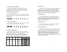
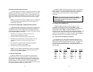
3.3 SPECIAL CONFIGURATION
If your installation requires special configuration of the Model
1060RC, use the table below as a guide. This table shows all possible
Model 1060RC switch settings. Following the table are brief
descriptions of the Control Input, Control Output, +Voltage Output and
Carrier Controlled by (C
in
) parameters shown in the table below.
*Multiple input pins are "or-tied"—if any input goes low, carrier is dropped
5
DCE 4 8 6 Disabled ON ON ON OFF OFF OFF OFF
DCE 4 8 6 Enabled ON ON ON OFF OFF OFF ON
DCE 4,11,20* 8 6 Disabled OFF ON ON ON OFF OFF OFF
DCE 4,11,20* 8 6 Enabled OFF ON ON ON OFF OFF ON
DCE 4 6 8 Disabled ON OFF OFF OFF ON ON OFF
DCE 4 6 8 Enabled ON OFF OFF OFF ON ON ON
DCE 4,11,20* 6 8 Disabled OFF OFF OFF ON ON ON OFF
DCE 4,11,20* 6 8 Enabled OFF OFF OFF ON ON ON ON
Control Control +Voltage Carrier
Mode Input Output Output Controlled
(DCE/DTE) (C
In
)(C
Out
)(V
Out
) by (C
In
) 1234567
Switch Settings