


APPENDIX C
FACTORY REPLACEMENT PARTS
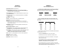
The Patton Model 1060RC rack system features interchangeable
rear half cards, power cords/fuses for international various operating
environments and other user-replaceable parts. Model numbers and
descriptions for these parts are listed below:
Patton Model #
Description
1000RPEM..........................120/240V Rear Power Entry Module
1000RPSM-2.......................120/240V Front Power Supply Module
1000RPEM-DC ...................DC Rear Power Entry Module
1000RPSM-48A ..................48V Front Power Supply Module
1000RPEM-V ......................120/240V CE Compliant Rear Power
Entry Module
1000RPSM-V ......................120/240V CE Compliant Front Power
Supply Module
0805US ...............................American Power Cord
0805EUR.............................European Power Cord CEE 7
0805UK ...............................United Kingdom Power Cord
0805AUS.............................Australia/New Zealand Power Cord
0805DEN.............................Denmark Power Cord
0805FR ...............................France/Belgium Power Cord
0805IN.................................India Power Cord
0805IS.................................Israel Power Cord
0805JAP..............................Japan Power Cord
0805SW ..............................Switzerland Power Cord
05R16FPB1.........................Single Width Blank Front Panel
05R16FPB4.........................4-Wide Blank Front Panel
05R16RPB1 ........................Single Width Blank Rear Panel
05R16RPB4 ........................4-Wide Blank Rear Panel
0821R4................................400 mA Fuse (5x20mm)
Littlefuse 239.400 or equivalent
0821R2................................200 mA Fuse (5x20mm)
Littlefuse 239.200 or equivalent
056S1..................................Set of 16 #4 pan head screws/washers
APPENDIX D
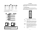
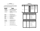
INTERFACE STANDARDS
21 22
1- (FG) Frame Ground
2- (TD) Transmit Data To 1060RC
3- (RD) Receive Data From 1060RC
4- (RTS) Request to Send To 1060RC
5- (CTS) Clear to Send From 1060RC
6- (DSR) Data Set Ready From 1060RC
7- (SG) Signal Ground
8- (DCD) Data Carrier Detect From 1060RC
To 1060RC Data Term. Ready (DTR) - 20
DIRECTION STANDARD RS-232C/V.24 "DCE" SETTING DIRECTION
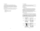
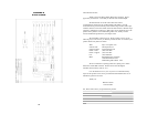
EIA/TIA-561 REFERENCE - 8 Wire RJ-45
Contact Number Circuit Description
1 125 Ring Indicator or DSR
2 109 Received Line Signal Indicator
3 108 / 2 DTE Ready
4 102 Signal Common
5 104 Received Data
6 103 Transmitted Data
7 106 Clear to Send
8 105 / 133 Request to Send / Ready for Receiving
PATTON MODIFIED MODULAR INTERFACE - 10 Wire RJ-45
Contact Number Circuit Description
1 N/A Receive Clock (Not Used for 1060RC)
2 125 Ring Indicator or DSR
3 109 Received Line Signal Indicator
4 108 / 2 DTE Ready
5 102 Signal Common
6 104 Received Data
7 103 Transmitted Data
8 106 Clear to Send
9 105 / 133 Request to Send / Ready for Receiving
10 N/A Transmit Clock (Not Used for 1060RC)