


10
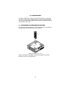
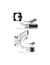
6. Connect the Ethernet interface (refer to section 3.4, “Connecting the
10/100Base-T Ethernet Interface” on page 11).
3.3 CONNECTING THE TWISTED-PAIR LINE INTERFACE
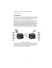
The VLINK modem supports communication between two peer Ethernet
LAN sites over a distance of up to 6,000 ft (1.83 km) over 24 AWG
(0.5 mm) twisted-pair wire.
Note
Actual distance and link performance may vary depending on
the environment and type/gauge of wire used.
Follow the steps below to connect the VLINK modem VDSL interfaces.
Note
The VLINK modem units work in pairs. One of the units must be
a CO (Central Office), and the other unit must be a CP (Cus-
tomer Premise). It does not matter which end is the CO and
which is the CP. The link is always initiated by the CP. As long as
the CO is powered on, the CP can establish a link by being pow-
ered on or by having its power reset.
1. To function properly, the two VLINK modems must be connected
together using twisted-pair, unconditioned, dry, metal wire, between
19 (0.9mm) and 26 AWG (0.4mm). Leased circuits that run through
signal equalization equipment are not acceptable.
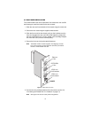
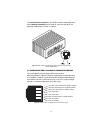
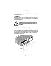
2. The VLINK modem is equipped with two interface jacks that can be
used on the VDSL interface, an RJ-45 or a terminal block. These
VDSL interfaces are a two-wire interface. Observe the signal/pin rela-
tionships on the VLINK modem's VDSL interface jacks.
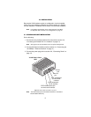
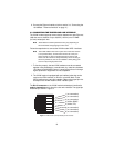
The
RJ-45 connector
on the VLINK modem's twisted pair interface
is
polarity insensitive
and is wired for a two-wire interface. The signal/pin
relationship is shown in Figure 4.
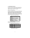
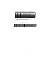
Figure 4.
VLINK modem (RJ-45) twisted pair line interface.
1 (no connection)
2 (no connection)
3 (no connection)
4 (2-Wire RING)
5 (2-Wire TIP)
6 (no connection)
7 (no connection)
8 (no connection)
1
2
3
4
5
6
7
8