


12
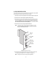
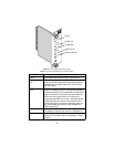
3.5 CONNECTING THE POTS/ISDN LINE
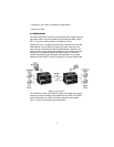
The RJ-45 port labeled “POTS/ISDN” is the POTS/ISDN interface. A tele-
phone or an ISDN device may be connected to this port and carried over
the VDSL line. The units do not need power for the POTS interface to
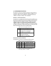
work. The RJ-45 connector in the VLINK modem’s POTS/ISDN interface
is wired as shown in Figure 7.
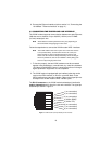
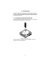
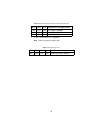
Figure 7.
VLINK (RJ-45) POTS/ISDN interface
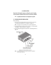
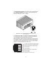
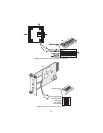
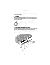
3.6 CONNECTING POWER
An external AC or DC power supply is available separately. This connec-
tion is made via the barrel jack on the rear panel of the VLINK standalone
modem. No configuration is necessary for the power supply (See Appen-
dix B for domestic and international power supply and cord options).
DC power (supplied via the power supply jack to the VLINK modem)
must meet the following requirements; DC power supplied must be regu-
lated +5VDC ±5%, 1.0A minimum. Center pin is +5V. The barrel type
plug has a 2.5/5.5/10mm I.D./O.D./Shaft Length dimensions.
The VLINK modem does not have a power switch, so it powers up as
soon as it is plugged in.
WARNING
There are no user-serviceable parts in the VLINK
modem.Fuse replacement should only be performed
by qualified service personnel. Contact Patton Elec-
tronics Technical support at (301) 975-1007 for more
information.
1 (no connection)
2 (no connection)
3 (no connection)
4 (2-wire RING)
5 (2-wire TIP)
6 (no connection)
7 (no connection)
8 (no connection)
1
2
3
4
5
6
7
8