


9
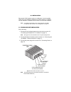
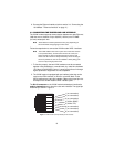
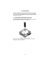
3.2 RACK CARD INSTALLATION
The VLINK modem rack card comprised a front card and a rear card.Do
the following to install the cards into the rack chassis:
1. Slide the rear card into the back of the chassis along the metal rails.
2. Secure the rear card using the supplied metal screws.
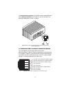
3. Slide the front card into the chassis until you feel resistance as the
front card engages the rear card. When that happens,
gently
push
the front card forward until it is fully seated in the card-edge recepta-
cle of the rear card (it should
click
into place).
4. Secure the front card using the captive fasteners.
Note
The Model 1001R14 chassis supports “hot swapping” of cards,
so it is not necessary to power down the rack when you install or
remove a VLINK modem rack card.
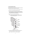
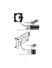
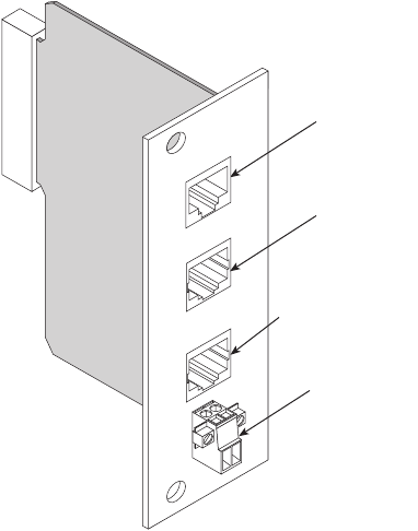
Figure 3.
VLINK modem rack card
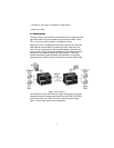
5. Connect the line interface between the units (refer to section 3.3,
“Connecting the Twisted-Pair Line Interface” on page 10)
Note
See Figure 3 for the rack card’s panel arrangements.
VDSL Link
Ethernet
POTS/ISDN
1068RC
Ethernet
Port
POTS/ISDN
Port
VDSL Link
RJ-45 interface
VDSL Link
terminal block