


12
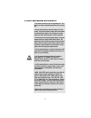
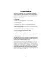
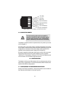
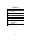
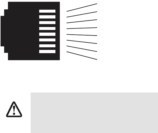
Figure 4.
Model 2172A 10/100Base-T RJ-45 Connector Pinout.
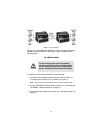
3.3 CONNECTING POWER
The Model 2172A does not have a power switch, so it powers up as soon
as it is plugged in.
An external AC or DC power supply is available separately. This connec-
tion is made via the barrel jack on the rear panel of the Model 2172A. No
configuration is necessary for the power supply (See Appendix B for
domestic and international power supply and cord options).
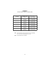
DC power (supplied via the power supply jack to the 2172A) must meet
the following requirements; DC power supplied must be regulated
+5VDC ±5%, 1.0A minimum. Center pin is +5V. The barrel type plug has
a 2.5/5.5/10mm I.D./O.D./Shaft Length dimensions.
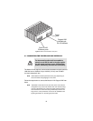
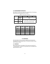
4.0 CONFIGURATION
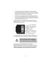
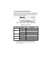
The Model 2172A has four DIP switches (S1) for configuring the unit for a
wide variety of applications. This section describes switch locations and
explains the different configurations.
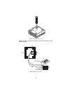
4.1 CONFIGURING THE HARDWARE DIP SWITCHES
Using a small flat-tip screwdriver, remove the protective cover located on
the underside of the Model 2172A (see Figure 5).
The Interconnecting cables shall be acceptable for
external use and shall be rated for the proper applica-
tion with respect to voltage, current, anticipated tem-
perature, flammability, and mechanical serviceability.
1 TX+/RX+
2 TX-/RX-
3 RX+/TX+
4 (no connection)
5 (no connection)
6 RX-/TX-
7 (no connection)
8 (no connection)
1
2
3
4
5
6
7
8
CAUTION