


14
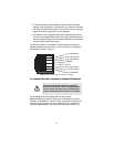
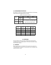
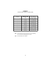
4.2 CONFIGURING DIP SWITCH S1
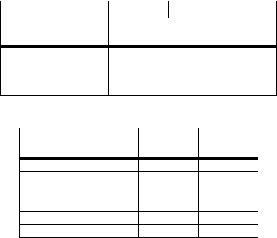
DIP switch S1 is where you configure the CopperLINK line. The following
tables describe the configuration for the 2172A.
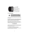
5.0 OPERATION
Once the Model 2172As are properly installed, they should operate
transparently. No user settings required. This section describes reading
the LED status monitors.
5.1 POWER UP
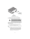
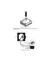
Before applying power to the Model 2172A, please review section 3.3,
“Connecting Power” on page 12 to verify that the unit is connected to the
appropriate power source.
Table 1:
2172A Firmware Configuration
Position
S1-1 S1-2 S1-3 S1-4
Master/
Slave
Rate
ON
Slave
(CPE)
4/1, 15/2, 50/2, 10/10, 25/25, 50/50
Rate Control (See table below).
OFF Master
(CO)
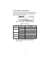
S1-2
S1-3 S1-4
Rate
(DS/US)
*
*. DS = Downstream, US = Upstream
OFF
OFF OFF 4/1
ON OFF OFF 15/2
OFF ON OFF 50/2
ON ON OFF 10/10
OFF OFF ON 25/25
ON ON ON 50/50