


31
32
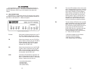
Loop Timeout
The Loop Timeout setting can be set to one of the following:
00:05 = five minutes
00:10 = ten minutes
00:15 = fifteen minutes
00:30 = thirty minutes (default setting)
00:45 = forty-five minutes
01:00 = one hour
01:30 = 90 minutes
02:00 = two hours
03:00 = three hours
NEVER = forever—the unit will remain in loopback without user
intervention.
Tx Data Clock
This option selects the clock that is used to accept the Transmit
Data from the DTE interface. Standard DTE interfaces will transmit
data with respect to the External Clock. In some cases a DTE interface
will transmit with respect to the Transmit clock sent out from the 2720.
Please review the information provided with your DTE equipment for
more information on its' operation. In most cases when there are errors
on the line only in the direction of the transmit data either Tx Data
Clock or Tx Clock Invert can be changed to solve the problem.
Tx Clock Invert
This option allows the user to invert the transmit clock originating
in the 2720. When Tx Data Clock is set for transmit clock, it may be
necessary to invert the transmit clock to allow for cable delays.
Set to Default Configuration
You may set the NetLink-T1™ to its factory default configuration,
except for the header lines and the password, by executing the Set to
Default Configuration command.
44..00 IINNSSTTAALLLLAATTIIOONN
The Model 2720 is equipped with DTE, network, and power inter-
faces. This section briefly describes connection to each.
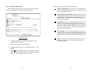
4.1 DTE INTERFACE CONNECTION
The DTE interface is a V.35 DCE presented as an M/34 male con-
nector. This interface is designed to plug directly into a DTE interface
(See Appendix D for V.35 interface pin assignments).
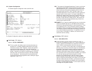
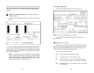
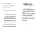
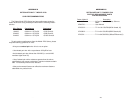
4.2 NETWORK INTERFACE CONNECTION
The Network Line Interface is an eight position keyed modular jack
configured as a RJ-48C. This interface will need to be configured to
match the line parameters (i.e. framing, line coding, etc.) supplied by
the central office.
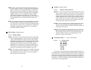
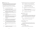
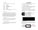
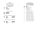
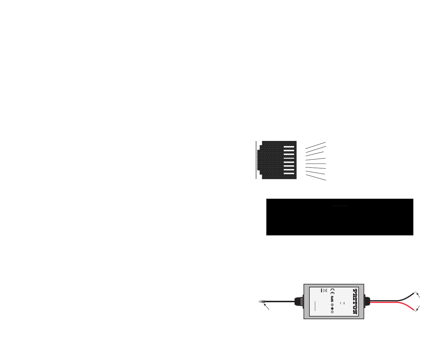
4.3 DC POWER SUPPLY
The 36-60 VDC DC to DC adapter is supplied with the DC version of
the Model 2720. The black and red leads plug into a DC source (nomi-
nal 48VDC) and the barrel power connector plugs into the barrel power
supply jack on the 2720.
Figure 2. Model 2720 twisted pair lineinterface.
1 RX Data (TIP)
2 RX Data (RING)
3 (no connection)
4 TX Data (TIP)
5 TX Data (RING)
6 (no connection)
7 (no connection)
8 (no connection)
1
2
3
4
5
6
7
8
NOTE:
If the Model 2720 is being used for private short range
modem applications, the twisted pair cable connected to
its port will need to be a crossover cable. See Appendix
D for Interface pin assignments.
} From Network
} To network
To Power
Supply Jack
To -48VDC
Source
-Vin
+Vin
SWITCHING POWER SUPPLY
MODEL : SYD1106-0505
INPUT : 36-60V 0.2A MAX
OUTPUT : +5V 1.0A
OUTPUT POWER : 5W MAX
S/N: G01234567890
MADE IN CHINA BY SUNNY
Black lead (-V)
Red lead (+V)
Barrel power connector