


6
3.0 PPP Operational Background
PPP is a protocol used for multi-plexed transport over a point-to-point
link. PPP operates on all full duplex media, and is a symmetric peer-to-peer
protocol, which can be broken into three main components: 1. A standard
method to encapsulate datagrams over serial links; 2. A Link Control
Protocol (LCP) to establish, configure, and test the data-link connection; 3. A
family of Network Control Protocols (NCPs) to establish and configure dif-
ferent network layer protocols.
In order to establish communications over a point-to-point link, each end
of the PPP link must first announce its capabilities and agree on the param-
eters of the link’s operation. This exchange is facilitated through LCP
Configure-Request packets.
Once the link has been established and optional facilities have been
negotiated, PPP will attempt to establish a network protocol. PPP will use
Network Control Protocol (NCP) to choose and configure one or more net-
work layer protocols. Once each of the network layer protocols have been
configured, datagrams from the established network layer protocol can be
sent over the link. The link will remain configured for these communications
until explicit LCP or NCP packets close the link down, or until some external
event occurs.
The PPP Bridging Control Protocol (BCP), defined in RFC 1638,
configures and enables/disables the bridge protocol on both ends of
the point-to-point link. BCP uses the same packet exchange mecha-
nism as the Link Control Protocol (LCP). BCP is a Network Control
Protocol of PPP, bridge packets may not be exchanged until PPP has
reached the network layer protocol phase.
3.1 APPLICATIONS
In situations where a routed network requires connectivity to a
remote Ethernet network, the interface on a router can be configured
as a PPP IP Half Bridge. The serial line to the remote bridge functions
as a Virtual Ethernet interface, effectively extending the routers serial
port connection to the remote network. The bridge device sends bridge
packets (BPDU's) to the router's serial interface. The router will receive
the layer three address information and will forward these packets
based on its IP address.
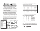
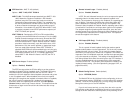
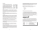
Figure 1 shows a typical Cisco router with a serial interface configured
as a PPP Half Bridge. The router serial interface uses a remote device that
supports PPP bridging to function as a node on the remote Ethernet net-
work. The serial interface on the Cisco will have an IP address on the
same Ethernet subnet as the bridge.
2.0 GENERAL INFORMATION
Thank you for your purchase of this Patton Electronics product. This
product has been thoroughly inspected and tested and is warranted for One
Year parts and labor. If any questions arise during installation or use of the
unit, contact Patton Electronics Technical Services at (301) 975-1007.
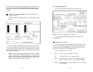
2.1 FEATURES
• Terminates T1/FT1 Circuits over a 4-Wire RJ-48C interface
• 10Base-T Ethernet bridge
• PPP (Point to Point Protocol, RFC 1661) with Bridge Control
Protocol (RFC 1638)
• Unstructured Rates at 1.544 Mbps
• D4 or ESF Framing Modes
• Supports AMI or B8ZS/B7ZS Line Coding
• Configuration via Software Control Port or Internal DIP Switches
• Six Easy-to-Read LED Indicators Monitor Data & Diagnostics
• Internal, External or Receive Recover Clocking
• Also Operates as a High-Speed Point-to-Point Modem
• Made in USA
2.2 GENERAL PRODUCT DESCRIPTION
The
NetLink-T1™
Model 2720 Series are single port T1/FT1
CSU/DSUs that provide high-speed WAN connectivity. Plugging directly into
the serial WAN port of a switch, router or multiplexer, the NetLink-T1™ pro-
vides T1 or FT1 access at connection data rates of 1.544 Mbps, nx64, and
nx56 (n=1 to 24 channels). The Netlink-T1™ is an excellent choice when
terminating leased line services, Frame Relay backbones, internet access
as well as LAN-to-LAN services.
The Netlink-T1™ provides digital access to a local WAN service
provider or directly between two facilities over a dedicated 4-Wire circuit.
WAN bandwidth, framing and coding options are programmed via externally
accessible DIP switches or via a VT-100 type terminal using the rear-
mounted EIA-232 Control Port. Netlink-T1™ supports D4/ESF framing
options and AMI/B8ZS/B7ZS line coding. Netlink-T1™ also supports a full
range of system and diagnostic features that make system setup easy.
The NetLink-T1™ provides T1 terminations over a modular RJ-48C jack
and comply with jitter tolerance capabilities as specified in ANSI T1.403 and
AT&T TR62411. External power options include 120VAC and universal
interface 100-240VAC. 48VDC and rack card versions are also available.
5