


11
12
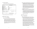
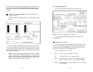
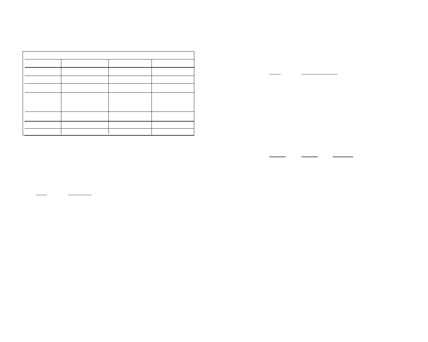
3.1.2 Switch S1
The chart below shows the default configurations for Switch S1. A
description of all S1 options follows this table.
Switch S1-1: RDL Type
Switch S1-1 selects the type of Remote Digital Loopback that the
2720 will initiate when the RDL is initiated from this unit. The 2720 will
respond to both the V54 and the CSU loopback regardless of the set-
ting of S1-1
S1-1
RDL Type
On Initiate a V.54 RDL loop when selected
Off Initiate a CSU loopback when selected
Switch S1-2: Reserved
Switch S1-3: Tx Clock Invert
Switch S1-3 allows the user to invert the transmit clock originating
in the 2720. When S1-2 is set for transmit clock, it may be necessary
to invert the transmit clock to allow for delays due to long cables.
S1-3 Tx Clock Invert
On Transmit clock is inverted
Off Transmit clock is normal
Switches S1-4 and S1-5: Line Build Out
Use Switches S1-4 and S1-5 to set the Line Build Out (LBO). The
Line Build Out varies the pulse shape and attenuation of the signal
sent to the network. The amount of Line Build Out depends on
NetLink™ T1’s distance to the last repeater. The telephone company
providing the service will advise on the amount of LBO necessary. In
most cases the default setting will suffice.
SW1-4 SW1-5 Function
Off Off -(0dB)
On Off -7.5dB
Off On -15.0dB
On On -22.5dB
Switch S1-6 Through S1-8: Reserved
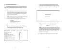
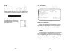
S1 SUMMARY TABE
Position Function Factory Default Selected Option
S1-1
RDL Type
On
S1-2
Reserved
On
S1-3
Tx Clock Invert
Off
S1-4
Line Build Out
Off
S1-5 Off
S1-6
Reserved
Off
S1-7
Reserved
Off
S1-8
Reserved Off
V.54 RDL
Normal
0dB