


33
34
55..00 OOPPEERRAATTIIOONN
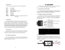
Once the NetLink-T1™ is installed and configured properly it is
ready to place into operation. This section describes the function of
the LED indicators, and the use of the loopback and pattern test
modes.
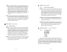
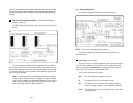
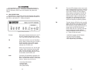
5.1 LED DESCRIPTIONS
The NetLink-T1™ is equipped with six LED indicators that monitor
the status of communication. Figure 12 (below) shows the location of
the LEDs on the NetLink-T1™ Series front panel.
T1 Link Solid green indicates that the end to end TI
link is up. Signifying that the link is active.
The TI link LED is off when the link is down
TD When the unit sends a one, the TD LED is
green. When it sends a zero, the TD LED is
orange. Moreover, the TD LED is active
only in active DS0 channels. In inactive
channels, the TD LED is off.
RD When the unit receives a one, the RD LED
is green. When it receives a zero, the RD
LED is orange. Moreover, the RD LED is
active only in active DS0 channels. In inac-
tive channels, the RD LED is off.
ALM The alarm LED indicates the presence of a
Blue or Yellow Alarm, or Out of Frame con-
dition. The ALM LED will blink on every half-
second. Alarms may occur due to:
•
Loss of Synchronization
• Loss of Frame
• AIS (Blue Alarm)
• RAI (Yellow Alarm)
ER The error LED indicates various error condi-
tions, including framing bit errors, excessive
zeros, controlled slips, severe errors, or bit
errors (when sending V.52 test patterns).
When sending a test pattern, the LED will
remain lit if the unit does not receive the
identical pattern. When it receives the cor-
rect pattern, the LED will turn off. If error
insertion is on, the LED will blink once a
second if everything is operating properly.
TM The test indicator LED blinks with a specific
pattern depending on the type of test mode.
When the unit is in local analog loop, the
LED will blink on briefly. When the unit is in
remote loop, the TM LED will blink off
briefly. When the unit is sending a test pat-
tern or is putting the remote unit into
V.54/CSU loopback, the TM LED will stay
on. These are the test modes:
• V.54/CSU Loopback & V.52 Patterns
• D4 Line Loop (CO initiated)
• ESF Line Loop (CO Initiated)
• ESF Payload Loop (CO Initiated)
Figure 3: 2720/C Front Panel