


3060/V24
102001UA
2-2
INSTALLATION AND OPERATIONS MANUAL
SETUP & INSTALLATION
PATTON ELECTRONICS CO.
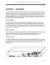
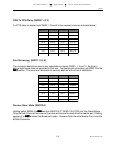
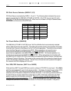
Switch 24 - All to
ONON
ONON
ON
RX Clock Source = Master
Contention Mode = Priority
Switch 25 - All to
ONON
ONON
ON
Sub-Channel Activity Indicated by Interface Control (RTS/DCD)
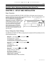
If the system application requires one or more of the default settings to be changed, it will be
necessary to remove the top cover of the enclosure to access and change the DIP switches
located on the printed circuit board.
Disassembly
Remove the top cover by removing the phillips head screws located on the left and right sides
of the 3060/V24 (CTS MD-V.24/TCB). DTE/DCE switches SW7 through SW20, interface
Jumpers J4 through J12 and configuration switches SW21 through SW25 are located on the
PCB as indicated on the strapping guide in the Appendix of this manual. After the switch
selection activity is completed,
re-install the top cover BEFORE connecting to a AC
power source
.
Installation
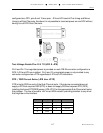
Select an appropriate location accessible to and within six feet of an AC power outlet, the
outlet must have a ground pin receptacle for product warranty. The DCE-to-DTE cabling
between each attached device and the 3060/V24 (CTS MD-V.24/TCB) should be “Straight
Through”, shielded and terminated with male connectors. Sub-Channels are marked PORT 1
through PORT 6, the Master Port is marked, MASTER DCE/DTE. If any terminal has a priority
service mode, ensure it is connected to the port connector designated "PORT 1" on the rear
panel of the 3060/V24 (CTS MD-V.24/TCB). Secure other terminals or Modems to be
serviced to the remaining “PORT” connectors. Connect the MODEM or TERMINAL to the
connector designated “MASTER DTE/DCE”.
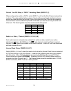
Equipment Grounding (SW21-8)
Switch SW21-8 provides for grounding interconnection in those systems requiring a
connection between (Frame Ground) and (Signal Ground). Connect ONLY if required.