


3060/V24
102001UA
2-7
SETUP & INSTALLATION
PATTON ELECTRONICS CO.INSTALLATION AND OPERATIONS MANUAL
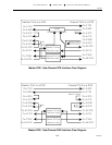
configured as a DTE, pins 9 and 10 are open. JP4 and JP5 control Plus Unreg and Minus
Unreg to all Sub-Channels, therefore it is not possible to have test power on one DCE without
having it on all DCE Sub-Channels.
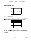
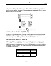
Test Voltage Enable Pins 9 & 10 (JP4 & JP5)
Pin 9 and Pin 10 unregulated power is provided on each DB-25 connector configured as a
DCE if JP4 and JP5 are installed. Pin 9 and 10 unregulated power is not provided to any
connector configured as a DTE regardless of JP4 and JP5 installation.
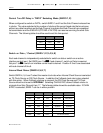
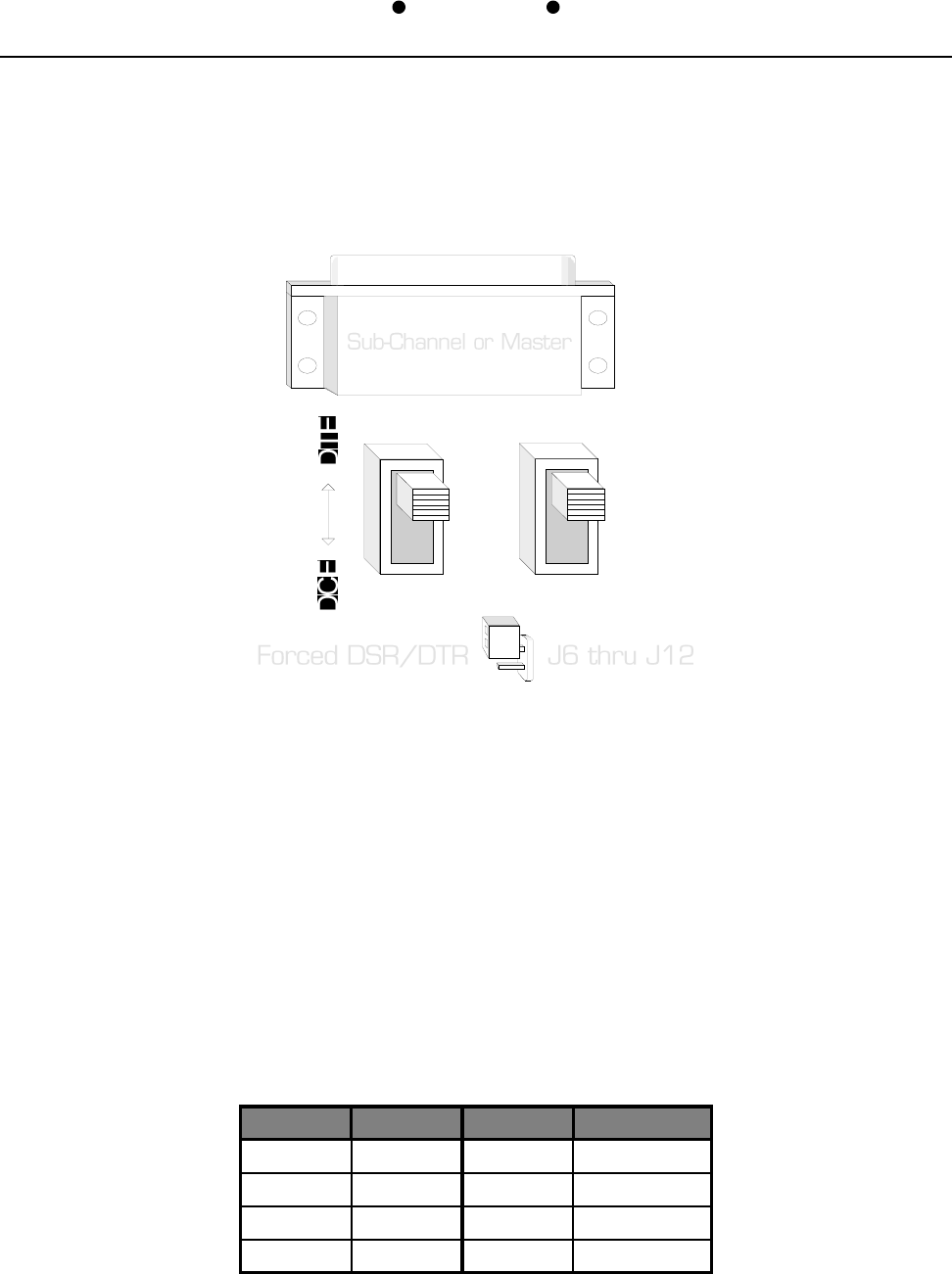
DTR / DSR Forced Active (JP6 thru JP12)
DTR is tied to DSR on each of the Sub-Channel ports. If the device connected does not
supply a DTR but requires DSR (DTE) or does not supply DSR but requires DTR (DCE),
installing the forced DTR/DSR jumper (JP6-JP12) for the appropriate Sub-Channel will solve
this problem. The line is forced to +8V via an 820Ω resistor, providing isolation to any driver
that might be on the interface.
Channel Jumper Channel Jumper
Master JP6 4 JP10
1 JP7 5 JP11
2 JP8 6 JP12
3 JP9