Installing the M-ATA
20
SmartLink M-ATA Getting Started Guide
2 • SmartLink installation
Installing the M-ATA
Note
The default password for the M-ATA is “
root”
.
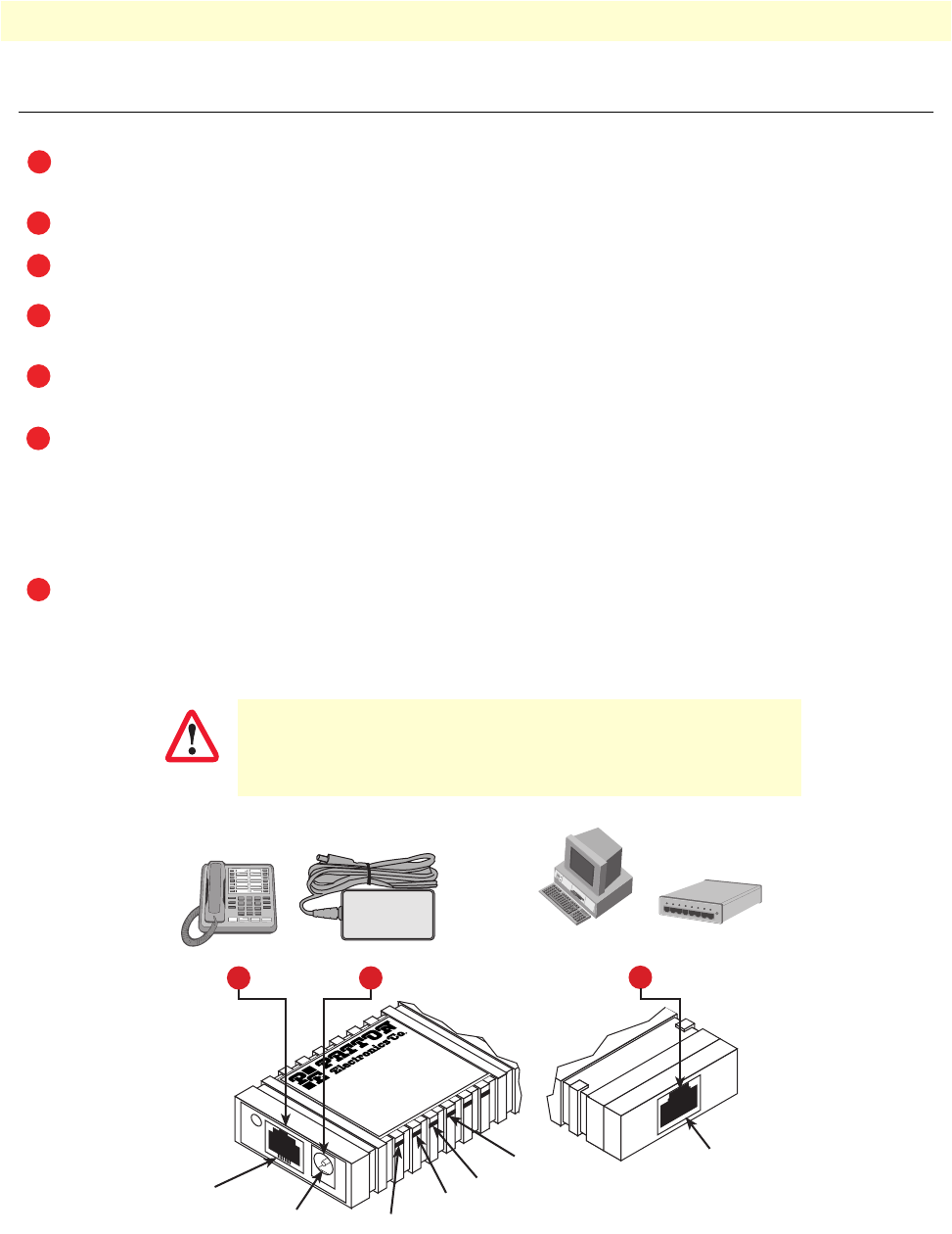
Figure 2.
SmartLink M-ATA
installation diagram
The unit should be installed in a dry environment with at least 2 inches (5 cm) of clearance at the sides,
front, and rear of the unit to allow air circulation for cooling.
Plug in the telephone (see figure 2).
Plug in the PC or LAN, or a LAN hub/switch.
Plug the power adapter into the power jack on the SmartLink M-ATA (see figure 2). Connect the other
end of the power cord to an appropriate AC power outlet.
Wait 30 seconds after powering the SmartLink M-ATA on, then verify that the green
Power
LED is lit
(see figure 2).
By default, the M-ATA will automatically request IP network settings from the LAN using DHCP. To
determine the IP address of the SmartLink, lift the handset off the attached analog phone and dial
* * * *
.
Dial
1 0 0 #
, listen to and record the IP address of the SmartLink. (To manually set the IP address, see
appendix E, “Voice prompt configuration” on page 85 for details).
Use a web browser to connect to the SmartLink M-ATA. The URL will be http://<ip address>. For
example, if the M-ATA IP address was
10.10.10.2
, the URL would be
http://10.10.10.2
.
Follow the directions of your voice service provider to set up
voice services.
IMPORTANT
Phone LED
Power LED
System LED
LAN LED
Gaithersburg, Maryland
M-ATA
Micro-Analog
Telephone Adapter
PHONE
LAN
SYSTEM
POWER
Power jack
Power adapter
LAN port
3
PC or
LAN
--or--
LAN
Hub/Switch
Phone
Phone jack
2 4
Front
view
Rear
view
