


Pelco Manual C842M (9/96) 9
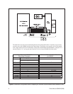
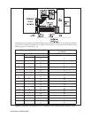
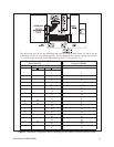
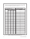
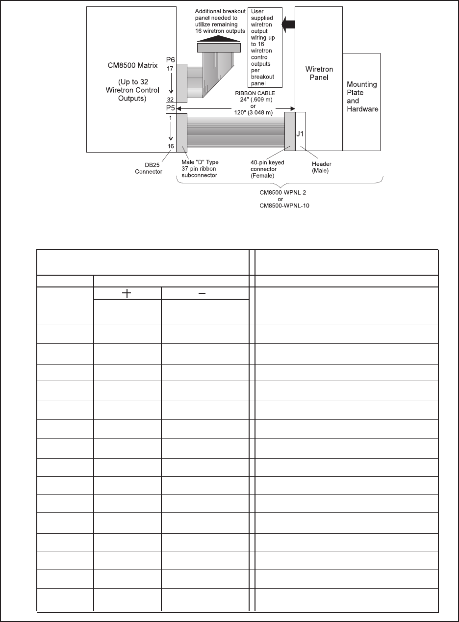
The table below lists the pin-out relationship between the wiretron panel header, J1, and P5 on the
CM8500 for the first 16 wire control positions. The pin mappings serve equally well for wire controls
17-32: P5 becomes P6 and the listed WIR numbers go from 17-32 instead of 1-16.
Wire Control Pin-outs 1-16/CM8500
Rear Panel-P5
WIR # Pin Number
11 ... 1
... 2 3
23 ... 5
... 4 7
35 ... 9
... 6 11
47 ... 13
... 8 15
59 ... 17
... 10 19
611 ... 21
... 12 23
713 ... 25
... 14 27
815 ... 29
... 16 31
920 ... 2
... 21 4
10 22 ... 6
... 23 8
11 24 ... 10
... 25 12
12 26 ... 14
... 27 16
13 28 ... 18
... 29 20
14 30 ... 22
... 318 24
15 32 ... 26
... 33 28
16 34 ... 30
... 35 32
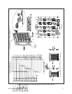
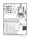
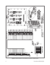
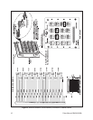
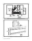
Figure 7. Installation Configuration and Pin Mapping for the CM8500 Wiretron Breakout Panel
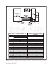
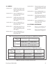
J1 Header Pin-out on Wiretron Breakout
Panel for CM8500
Pin Number