


TABLE OF CONTENTS
Section Page
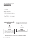
1.0 WARNINGS ........................................................................................................................................1
2.0 SCOPE ...............................................................................................................................................2
3.0 DESCRIPTION ...................................................................................................................................2
4.0 INSTALLATION ..................................................................................................................................2
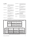
5.0 MODELS ..........................................................................................................................................13
6.0 OPTIONAL ACCESSORIES............................................................................................................. 13
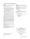
7.0 WARRANTY AND RETURN .............................................................................................................14
LIST OF ILLUSTRATIONS
Figure Page
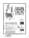
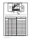
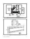
1 Alarm Breakout Panel Assembly Information–VA6000 Series ........................................................3
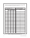
2 Installation Configuration and Pin Mapping for 4/8 Alarm Inputs-VA6000 Alarm Breakout Panel ........4
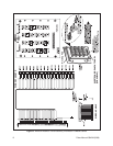
3 Installation Configuration and Pin Mapping for 12/20 Alarm Inputs-VA6000 Alarm Breakout Panel .... 5
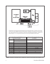
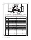
4 Alarm Breakout Panel Assembly Information–CM8500 Series .......................................................6
5 Installation Configuration and Pin Mapping for the CM8500 Alarm Breakout Panel .......................7
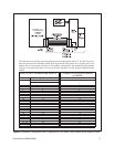
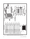
6Wiretron Breakout Panel Assembly Information–CM8500 Series ................................................... 8
7 Installation Configuration and Pin Mapping for the CM8500 Wiretron Breakout Panel................... 9
8Wiretron Breakout Panel Assembly Information–CM8500 Series ................................................. 10
9 Installation Configuration for the CM8500 Wiretron Breakout Panel............................................. 11
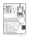
10 Rack Panel Mounting Plate Dimensions ....................................................................................... 11
11 Pin Mapping for the CM8500 Relay Breakout Panel..................................................................... 12
12 Simplified Part Number Ordering Tables .......................................................................................13
REVISION HISTORY
Manual # Date Comments
C842M 9/96 Original version created per ECO 96-044, 96-042.
ii Pelco Manual C842M (9/96)