


2 Pelco Manual C842M (9/96)
2.0 SCOPE
The information contained within this manual covers
the installation and operation of the Alarm Breakout
Panels for the VA6000 Series Switcher and the Alarm,
Wiretron and Relay Breakout Panels for the CM8500
Matrix system.
3.0 DESCRIPTION
VA6000
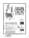
The Breakout Panels for the VA6000 Series provide a
convenient method for physically telescoping up to 20
alarm inputs down into the most appropriate of two
headers existing on the Alarm Breakout Panel board
for convenient connection to “D” type connectors on
the rear of the VA6000.
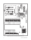
A ribbon cable connects one of the two available header
types (15-pin or 25-pin header) to the appropriate “D”
type connector, depending on alarm input population,
on the rear of the VA6000. Basically, two classes of rib-
bon cable are available: one for use with 4 and 8 alarm
input models and another for 12 or 20 alarm input mod-
els. Cables are further differentiated by length–24 inch
(.609 m) or 120 inch (3.048 m) lengths are available.
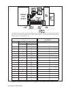
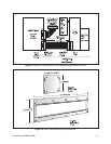
Additionally, each breakout panel assembly is shipped
from the factory installed on a single mounting plate
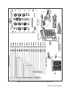
with appropriate mounting hardware. You should auto-
matically receive the correct breakout panel, ribbon
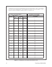
cable, mounting plate and hardware if you use Table 1
in Figure 12 as a guide while referencing all other ap-
propriate figures provided in the manual.
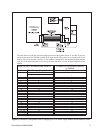
CM8500
The Breakout Panels for the CM8500 Matrix System
likewise provide a convenient method for physically
telescoping Alarm, Wiretron or Relay inputs down into
appropriate headers for eventual connection to “D” type
subconnectors on the rear of the CM8500 Matrix bay.
Unlike the VA6000 which is populated with two head-
ers, each with different pin-outs on one breakout panel,
the CM8500 utilizes three different breakout panels
populated with only one header, with header pin-out
configurations for the type of breakout panel being used:
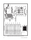
Alarm, Wiretron or Relay. For the CM8500, Breakout
panels for Alarm and Wiretron inputs utilize, in each
case, a single 40-pin header, while Relay Breakout pan-
els incorporate a single 50-pin header.
As was the case for the VA6000, all telescoped inputs
for breakout panels used with the CM8500 are con-
nected via the appropriate onboard header to existing
“D” type connectors on the rear of the CM8500 Matrix
bay via ribbon cables.
The 24 inch (.609 m) and 120 inch (3.048 m) length
ribbon cable assemblies for the 40-pin header type con-
nectors have the same configuration and can be used
with either the Wiretron Breakout Panel or the Alarm
Breakout Panel.
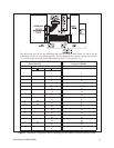
The ribbon cable used with the 50-pin header (also avail-
able in the same lengths) is used only with the Relay
Breakout Panel for the CM8500 system. Reference
Table II, Figure 12 as a guide for ordering information
related to CM8500 breakout panels while referencing
other appropriate figures in the manual.
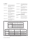
NOTE: When working with a CM8500 Ma-
trix System, additional subassemblies may be
required (if not already installed) on the
CM8500 side of the installation in order to uti-
lize the Alarm, Wiretron and Relay connectors
on the rear of the CM8500 Matrix bay. These
are:
CM8506 Communication circuit card to al-
low the CM8500 to communicate
with Wiretron receiver/drivers.
Mounts to Buffer Card.
CM8532 32 alarm/32 relay circuit card kit
to allow for direct monitoring of
32 alarms and the use of 32 relay
outputs programmable in software.
Consult your CM8500 manual (C501M) for in-
stallation requirements and any related infor-
mation, if needed.
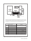
4.0 INSTALLATION
Breakout panels come from the factory installed on
single mounting plates; an appropriate ribbon cable is
included with the assembly. The Breakout panel and
plate can be mounted in any convenient, accessible lo-
cation. Once mounted, all user supplied wiring inputs
(alarm, wiretron or relay) can be connected and then
the supplied ribbon cable can be run between the header
on the breakout panel and the appropriate “D” type con-
nector on the equipment being used, whether VA6000
or CM8500.
Once the panels are physically mounted and all wires
and cables are run, the product is ready for use.