


12 Pelco Manual C842M (9/96)
1 ... ... 1
1 ... 2 ... 2
... ... 3 3
4 ... ... 4
2 ... 5 ... 5
... ... 6 6
7 ... ... 7
3 ... 8 ... 8
... ... 9 9
10 ... ... 10
4 ... 11 ... 11
... ... 12 12
13. ... ... 13
5 ... 14 ... 14
... ... 15 15
16 ... ... 16
6 ... 17 ... 17
... ... 18 18
19 ... ... 19
7 ... 20 ... 20
... ... 21 21
22 ... ... 22
8 ... 23 ... 23
... ... 24 24
25 ... ... 25
9 ... 26 ... 26
... ... 27 27
28 ... ... 28
10 ... 29 ... 29
... ... 30 30
31 ... ... 31
11 ... 32 ... 32
... ... 33 33
34 ... ... 34
12 ... 35 ... 35
... ... 36 36
37 ... ... 37
13 ... 38 ... 38
... ... 39 39
40 ... ... 40
14 ... 41 ... 41
... ... 42 42
43 ... ... 43
15 ... 44 ... 44
... ... 45 45
46 ... ... 46
16 ... 47 ... 47
... ... 48 48
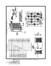
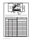
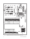
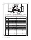
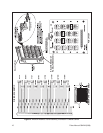
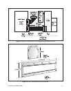
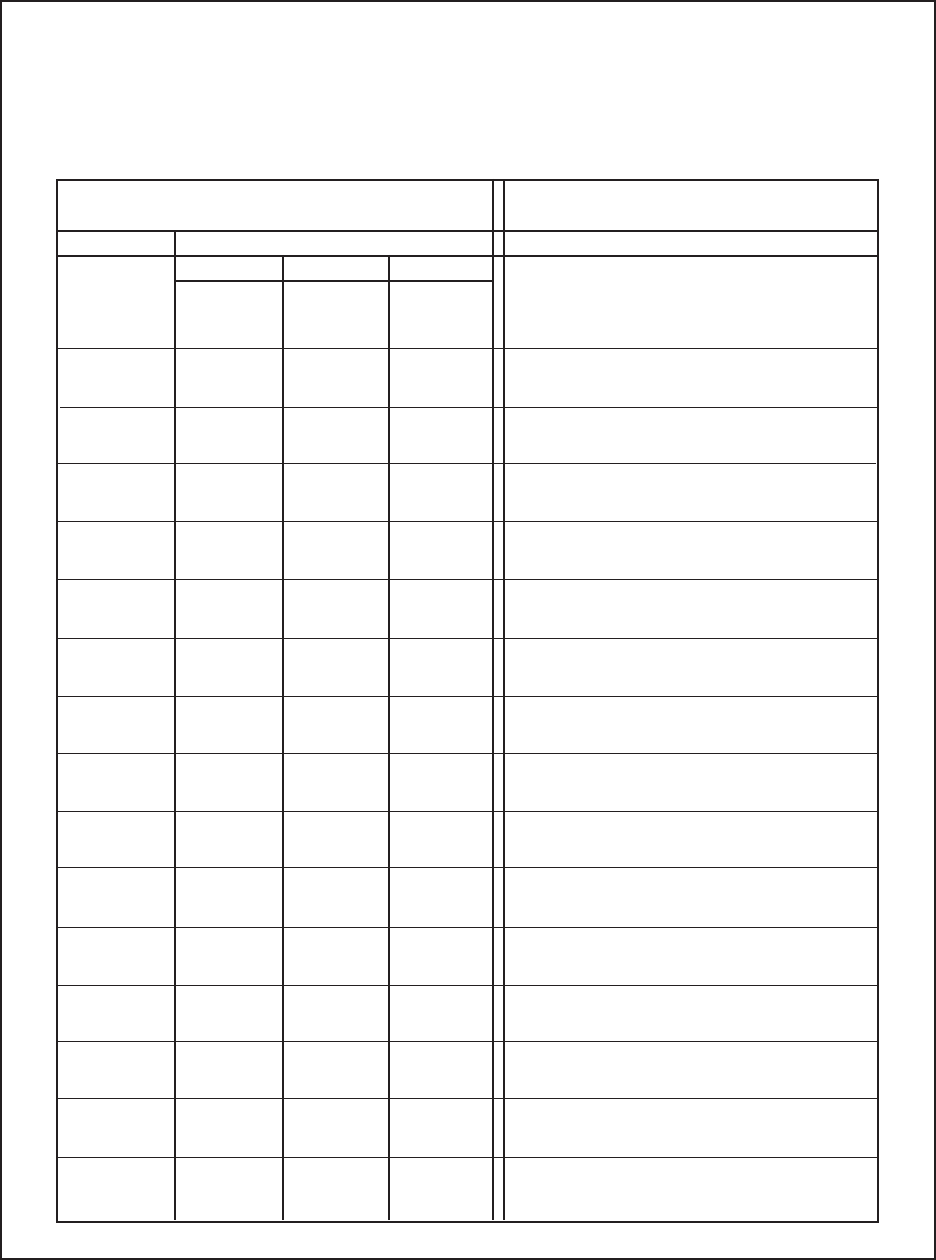
J1 Header Pin-out on Relay
Breakout Panel for CM8500
Relay 1-16 Pin-outs CM8500
Rear Panel-P1
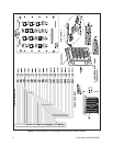
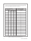
RELAY # Pin Number
NC NO COM
Pin Number
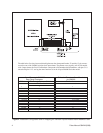
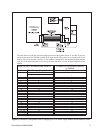
The table below lists the pin-out relationship between the relay panel header, J1, and P1 on the CM8500
for the first 16 relay output positions. The pin mappings serve equally well for relay outputs 17-32: P1
becomes P2 and the listed RELAY numbers go from 17-32 instead of 1-16.
Figure 11. Pin Mapping for the CM8500 Relay Breakout Panel