


Pelco Manual C842M (9/96) 5
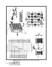
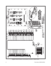
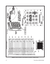
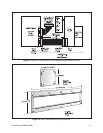
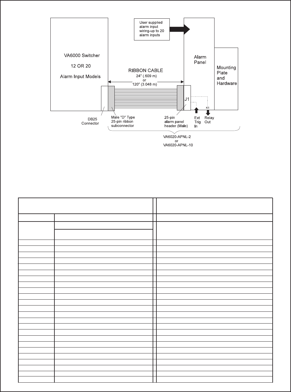
Figure 3. Installation Configuration and Pin Mapping for 12/20 Alarm Inputs-VA6000 Alarm Breakout Panel
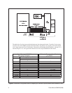
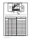
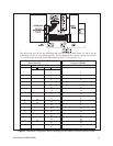
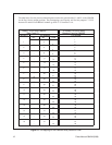
Alarm Pin-outs 1-16/CM8500 Rear Panel-P4
ALM # 25-Pin Female Conn. on Switcher
Pin Number
11 1
22 3
33 5
44 7
55 9
66 11
77 13
88 15
99 17
10 10 19
11 11 21
12 12 23
13 13 25
14 14 2
15 15 4
16 16 6
17 17 8
18 18 10
19 19 12
20 20 14
K1 - NO 21 16
K1 -COM 22 18
K1 - NC 23 20
Ext.Trig. 24 22
Comm 25 24
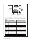
The table below lists the pin-out relationship between the alarm panel header, J1, and the 25-pin con-
nector on the rear of the VA6000 switcher for 20 input alarms. The pattern serves equally well for VA
models with 12 input alarms: the first 12 Pin Numbers correspond to like numbered ALM numbers
with pins 13-20 unused and pins 21-25 serving the same functions as in the 20 input VA6000 Switcher
models.
Pin Number
J1 Header Pin-out on Alarm Breakout
for CM8500