


6 C1518M-A (11/02)
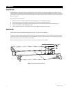
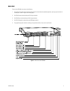
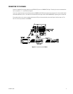
Figure 3. Rack-Mount Installation
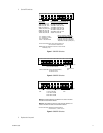
WIRING RELAYS
The relay unit has four groups of relay contacts. Each group represents 16 pairs of relay contacts:
• Group I – 1-8, 9-16
• Group II – 17-24, 25-32
• Group III – 33-40, 41-48
• Group IV – 49-56, 57-64
Each of the four groups contains two connectors with input mating plugs. The top connector is for the first eight pairs of relay contacts
and the bottom connector is for the last eight pairs of relay contacts. Each mating plug has 16 screw terminals and 16 pins. When you
place a wire into a pin, tighten the screw to secure it.
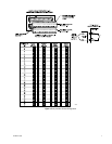
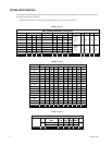
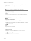
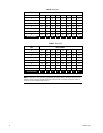
Refer to Figure 4 to determine the screw terminal number for a particular contact. The numbers that appear on the mating plugs in Figure
4 are for illustration only. The terminal positions on the actual physical plugs are not numbered.
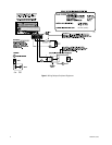
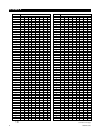
Refer to Figure 5 for wiring the relays to peripheral equipment.
00701
INSTALLATION
The following items are supplied:
• REL2064 Relay Interface Unit
• 120 VAC power cord
• 220 VAC power cord
• Pelco screwdriver
• 10-foot (3 m) straight RJ-45 cable (8-conductor)
•4 #10 screws with nylon washers
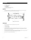
MOUNTING
Install the relay unit in a 19-inch rack. The unit occupies one rack unit (1.75 inches or 4.45 cm) of space. You can mount the relay unit to
something other than a standard 19-inch rack by relocating the rack ears to another location.