30 C1552M-C (7/07)
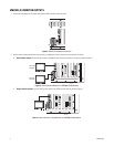
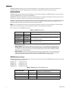
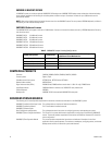
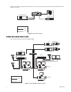
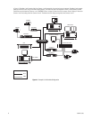
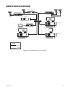
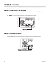
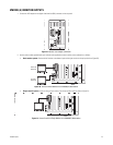
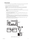
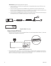
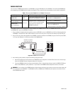
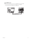
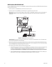
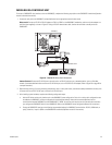
Internet Protocol: Complete the following steps (refer to Figure 28):
a. Connect the wall block to an RS-422 port on the networked device. If the networked device does not have an RS-422 port, use an
RS-232 to RS-422 converter.
b. Connect the IP network to the Ethernet port of the VMX300(-E); refer to IP-Based Devices on page 40 for detailed information.
c. Add the Pelco Keyboard (KBD300) driver and the keyboard to the VMX300(-E) server configuration, and select Internet Protocol as the
connection type (refer to the VMX300(-E) Server Configuration Manual for detailed instructions).
d. Configure the keyboard for CM6800 ASCII mode. Configure the remaining keyboard settings to match the communication settings on
the networked device (refer to the KBD300A Installation/Operation manual for instructions).
Figure 28. KBD300A: IP Connection
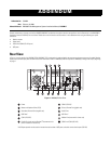
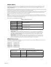
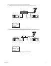
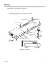
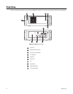
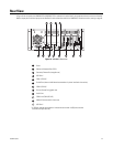
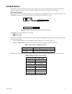
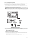
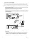
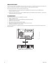
Configure the Keyboard DIP Switches
1. Remove the DIP switch cover plate on the rear of the keyboard. Switches 1 to 4 control the keyboard address. Switches 5, 7, and 8 control
the keyboard mode. The ON position is down; OFF is up.
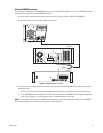
Figure 29. KBD300A Keyboard Rear Panel
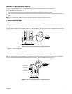
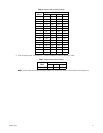
2. To set the keyboard address, move switches 1 to 4 to the appropriate position, as described in Table H. The address must be the same as
the address configured on the Communications tab (refer to the Add a KBD300A Keyboard section in the VMX300(-E) Server Configuration
Manual for more information). Each address on a particular serial port must be unique.
VMX300(-E)
1
2
3
4
8
7
6
5
12 VAC
KBD300A
NETWORKED DEVICE
WALL BLOCK
SERIAL DATA
NETWORK CONNECTION
NETWORK
N
O
12345678
KBD300A REAR PANEL