32 C1552M-C (7/07)
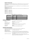
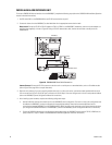
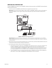
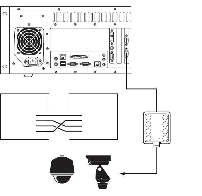
SPECTRA/ESPRIT CONTROL CONNECTIONS
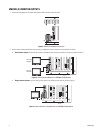
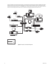
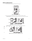
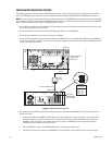
If you connected a Spectra or Esprit camera positioning system directly to a video input port on the VMX300(-E) workstation (-1 or -4 models
only), you must also connect a data cable to the VMX300(-E) workstation to provide direct camera control from the VMX300(-E).
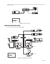
1. Use one of the COM ports on the VMX300(-E) workstation for the control connection. Using an RS-422 COM port requires a wall block
between the VMX300(-E) and the camera. If you use an RS-232 COM port, you will need an RS-232 to RS-422 converter (user-supplied) and
power supply.
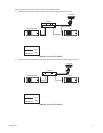
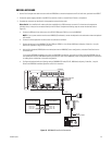
Use twisted pair wire to connect the Spectra or Esprit receivers to the COM port or the converter. You can daisy-chain (connect a series of
cameras) from the Rx+ and Rx- connections on the first Spectra or Esprit to additional units.
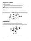
NOTE: The Spectra III
™
D protocol provides a feedback option. “Feedback” refers to positioning data that is sent from the camera to the
VMX300(-E). This positioning data rotates the camera icon viewed on the map in the VMX300(-E) client, based on the actual physical position
of the camera. To receive feedback from the Spectra III, you must also connect Rx+ and Rx- on the wall block to Tx+ and Tx- on the Spectra III.
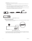
Figure 30. Spectra/Esprit Control Connections
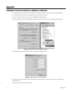
2. After installing system hardware, complete the following configuration steps (refer to the VMX300(-E) Server Configuration Manual for
detailed instructions):
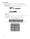
a. Change the settings for the VMX300(-E) COM port to match the communication settings on the camera (baud rate, parity, etc.).
Refer to the Appendix on page 42 for instructions.
b. Add the Pelco PTZ camera driver to the VMX300(E-) server configuration.
c. Add the PTZ device (the Spectra or Esprit camera) to the VMX300(E-) server configuration, using the following device properties:
(1) Communications tab, Connection Type: Select Direct Serial.
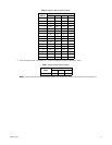
(2) Communications tab, Camera Address: Select the address that correspond to the DIP switch settings selected on the camera.
(3) Camera Model tab: Select the appropriate model and protocol; D protocol is recommended.
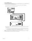
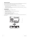
VMX300(-E)
RS-422
1
2
3
4
7
6
5
8
PIN 2 = Rx+
PIN 3 = Tx-
PIN 7 = Tx+
PIN 8 = Rx-
PIN 1 = Tx+
PIN 2 = Tx-
PIN 7 = Rx-
PIN 8 = Rx+
SPECTRA
ESPRIT
TO RECEIVERS
WALL
BLOCK
WALL BLOCK
PIN ASSIGNMENTS
VMX300(-E) COM 3 & 4
RS-422 PIN ASSIGNMENTS