


DSATX Manual Copyright 2006 Mpegbox.com Page 4 of 13
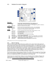
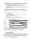
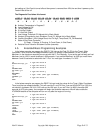
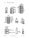
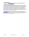
2.5. Detailed Connection Diagram
J8
J5
J7
J2
JP1
P1
P2
D8
J1
F1
Power Input
J5 Gnd: Ground Input, connect to the chassis or the (–) battery terminal
Vin: +12 Volts Input, connect directly to the (+) battery terminal
Acc: Accessory Input, Connect to a switched +12 volt supply wire (ignition or fuse box)
F1 Input Fuse: 20-Amp mini-automotive fuse (yellow)
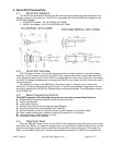
Power Output
J8 ATX12V: Connect to the 4-pin processor power connector on the motherboard
J7 ATXPWR: Connect to the 20-pin motherboard power connector and peripherals
J1 FAN: Connects to a 12 Volt 3-pin fan to cool the DSATX
Control
JP1 Pins G1, G2: Connects to Motherboard Power Switch Header (G2=Signal Output, G1=Gnd)
Pins F1, F2: Aux Connection (for Amp Enable or Slave Power Supply)
Pins E1, E2: SL_SEN (RESERVED)
Pins D1, D2: User Switch (will zero countdown timer when shorted)
Pins C1, C2: User1 (RESERVED)
Pins B1, B2: User0 (Shorting Jumper here enables Dumb PSU Mode)
Pins A1, A2: A1=+5V, A2=nReset (RESERVED)
P1* Countdown Adj: In Basic Mode, clockwise rotation adds time to the Countdown Timer (0-20m)
P2* Low Voltage Adj: In Basic Mode, clockwise rotation raises the low voltage threshold (10V-12V)
D8 LED indicator: Indicates Operation, Timer States, and Faults
J2 Serial Port: Enables Advanced Modes, field upgrades, and diagnostics
*Note: Do Not Over-Turn P1 and P2, only 270 degrees is available
2.6. Bench Testing
The DSATX can be tested in the lab before being installed into the vehicle. Certain details need to be
noted for proper bench testing. When connecting bench power use between 12 to 16 volts DC to Vin and
Gnd terminals for best results. Small jumper wires may be sufficient to turn on the DSATX alone; however
they will most likely not be adequate to run a computer. For the DSATX to turn on successfully, the bench
supply must be able to provide 2 amps of inrush current. Under full rated load the DSATX draws around
18 amps @ 12V input. 12-volt bench top power supplies capable of delivering this kind of load are
expensive and uncommon. Using 12 gauge or heavier wire will provide the best results. It is OK run a
jumper wire from VIN to ACC for bench testing and certain installations.
To aid in bench testing, a Shorting Jumper at location JP1 pins B1 and B2 will enable Dumb Power Supply
Mode. This will bypass the Startup/Shutdown sequencing and battery protection. ACC is not required and
the LED will indicate that the DSATX is providing power on all the output rails.
The best way to do successful bench testing is to use an adequately sized 12V battery. Bringing in the
battery from the car or using an extra one that has at least a 12-AmpHour capacity will be sufficient in
most cases. Do not connect a Car Battery Charger directly to the DSATX.