


DSATX Manual Copyright 2006 Mpegbox.com Page 5 of 13
Using the 12 volt output of an ATX AC-DC power supply is also a method for successful bench testing. By
shorting the Green Wire (PS_ON) of an ATX AC-DC power supply can provide the required current for
certain bench testing applications. Make sure minimum load requirements (on the AC-DC power supply)
are met if going this route.
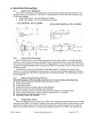
2.7. Quick Installation Steps
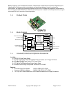
• Connect GND, and VIN with heavy gauge wire directly to the automotive batteries + and - terminals.
GND may also be connected with heavy gauge wire to the Chassis if desired.
• Connect the ATX Power Connector (J7/J8) to the Motherboard and any peripherals to the Molex
Connectors.
• Connect a case fan with standard 3-pin connector to J1 FAN (or assure adequate air flow).
• Connect the ACC line to a switched 12 volt connection in the car (or through a switch to a constant 12
volt battery connection). This connection does not need to be heavy gauge.
• Connect a 2-pin jumper cable between location G at JP1 and the Motherboards "Power On" header.
This will allow the DSATX to turn on and off the motherboard by simulating a power button press
(POLARITY MATTERS HERE).
• Set P1 to set the time before shutdown. Adjustable between 0-20 minutes by default in Basic Mode.
• Set P2 jumper to set the low voltage cutout voltage. To minimize this feature, set it to 10 volts (fully
counter clockwise). P2 is adjustable between 10-12 volts.
• Apply 12 volts to ACC by turning on the ignition or by flipping a switch and you’re ready to go!
3. User Guide
3.1. Theory of Operation
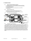
The basic idea of the DSATX is this: You want to put a computer in your car, but you don’t want to
worry about turning it on and off, you don’t want to worry about the temperature extremes, and you don’t
want to worry about the harsh automotive electrical environment. You also want to have the ability to go to
the gas station and have the computer still running while you pump and pay so when you come back you
don’t have to wait a boot-up. When you get home, you don’t want a dead battery. This power supply is the
only one on the market that allows you to do all these things and have full control of the settings.
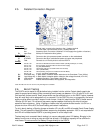
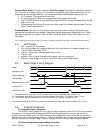
The following example will illustrate some of the features of Basic Mode and how it applies to an
automotive install. The DSATX is installed as described above. The user steps into the automobile and
turns on the key. ACC goes HI (12 Volts) as a result and the DSATX wakes up from Sleep Mode. The LED
turns on and it sends a startup pulse to the motherboard over the 2-pin jumper connected at JP1 pins G1
and G2. The computer now boots and is up and the DSATX is in Running Mode playing Mp3s, doing GPS
Navigation, etc. The automobile goes to the gas station and the driver turns off the key and ACC goes
LOW. The DSATX now starts the Countdown Timer (Countdown Mode) and the LED starts flashing once
per second. The driver gets back in the car, starts the car and the computer keeps playing the MP3s
without a hiccup. The DSATX now is back to Running Mode with the LED full on. The user then drives
home and turns off the car for the night. ACC goes low and the countdown timer starts and then expires.
The DSATX then sends a pulse again over JP1 pins G1 and G2 to shutdown the computer. The shutdown
pulse was successful and the computer turned off. The DSATX then goes to sleep and preserves battery
power.
3.2. Modes of Operation
Basic Mode: This is the factory default mode for the DSATX. In this mode the following options are
available:
• P1 and P2 adjustment pots are the only adjustable settings
• P1 adjusts the Countdown Timer, after ACC goes low the DSATX will wait between 0-20 minutes
(10 minutes by default, P1= 50%)
• P2 adjusts the Low Voltage Cutout (10-12 Volts, 11 Volts Default, P2=50%)
• No Serial Port Adapter is required
• A switch connected at JP1 pins D1,D2 (User Switch) will allow a quick shutdown