


DSATX Manual Copyright 2006 Mpegbox.com Page 6 of 13
Extended Basic Mode: This mode requires a Serial Port Adapter (see optional accessories above) to
use. This mode is entered by typing an ‘E’ Character to enable the writing of parameters then a ‘P’ for
Programming extended basic features. In this mode all the Basic Mode features apply as well as:
• P1 Countdown Timer range can be extended
• P1 and P2 adjustment pots can be bypassed and their values Hard Coded
• The VTURNON feature can be enabled allowing the DSATX to not send a startup pulse until the
engine is running
• Parameters set via the Serial Port stay even when power is completely disconnected. They are
stored in Non-Volatile Memory
Advanced Mode: This mode is simply going in and hard-coding various settings. Advanced setting
adjustments include button press duration, deep-sleep disable, temperature range adjust,* etc. These
settings are accesses by using the “Get” and “Set” commands. See the Serial Port Section for more
information.
*Note: modifying the temperature settings to allow higher operating temperatures will void the manufactures limited warranty.
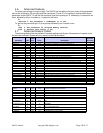
3.3. LED Codes
• OFF = System Off / Sleep Mode
• ON = Running Mode, the computer starts up in this mode (does not indicate computer is on)
• 1 blinks = Main Countdown Timer
• 2 blinks = Power Down (after shutdown pulse is sent)
• 3 blinks = N/A
• 4 blinks = Over or Under Temperature Condition. (Are you using a fan?)
• 5 blinks = Power Supply Overload or Fault (ACC must go low to clear a fault)
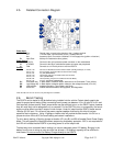
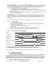
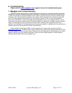
3.4. Basic Mode Timing Diagram
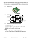
Accessory (J5)
Engine Running
+5V Standby
MB Power Switch (JP1)
Computer On
t2
t3
t1
User Switch (JP1)
Sleep Running Count Down Power Down Sleep
Mode
t1 = Time between ACC going High and the Computer Startup Pulse (TURNONDELAY). Default = 1s
t2 = Time between ACC going Low and the Computer Shutdown Pulse (Set by P1). Default = 600s (P1=50%)
t3 = Time between Computer Shutdown Pulse and +5V Standby OFF. Default = 90s Max, 2s Min
*User Switch is optional. The DSATX only listens for User Switch during the t2 Countdown Mode (LED = 1 blink)
3.5. Features Explained
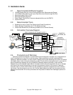
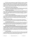
3.5.1. Startup/Shutdown Sequencer
The DSATX is has the ability to turn on and turn off the computer via the JP1 pins G1,G2 connection.
Connecting a 2-pin jumper wire will allow the DSATX to tell the motherboard to turn on and turn off by
simulating a power button press. The DSATX knows if the motherboard is on or off and will only send the
startup pulse if off and the shutdown pulse if on. This way the DSATX does not get into a weird state where it
turns the computer on/off when it wasn’t suppose to due to the user issuing a manual startup/shutdown.
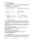
3.5.2. Input Voltage Monitoring and Engine Cranking