


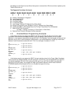
DSATX Manual Copyright 2006 Mpegbox.com Page 7 of 13
The DSATX is constantly monitoring the input voltage at the VIN terminal to make sure the conditions
are right to be operating a computer motherboard in the vehicle. The DSATX will not initially turn on unless the
voltage is above the value set by the P1 (or the serial adapter). Once the computer is up and running, the
DSATX can survive engine cranking for up to 10 seconds. If the voltage at VIN is outside the allowable range,
(battery too low) the DSATX will wait for sufficient charge before starting the computer and operating normally.
The DSATX will survive engine cranking under the majority of normal use cranks. If the battery is too old or too
depleted, there will be a point where no solution is capable of surviving engine cranking. Following the wire
gauge and installation guidelines will provide the best results.
3.5.3. Input Transient, and Reverse Voltage Protection
The DSATX has components that prevent the DSATX from being damaged from the harsh conditions
present in a motor vehicle. Transients above 24 volts (Load Dump) are shunted by the protection components.
Reverse voltage conditions will blow the fuse before damaging components on the DSATX.
3.5.4. Thermal Protection/Monitoring
The DSATX is equipped with a temperature sensor that monitors the ambient temperature around the
DSATX. The DSATX is programmed to only allow operation while the temperature is inside the window of -10c
to 55c. If outside this range, the LED will flash 4 times and the DSATX will not provide power. Once the out of
range condition goes away, the DSATX will behave like ACC was applied right at that point. This protects the
DSATX, and the computer hardware from temperature extremes and potentially damaging over and under
temperature conditions.
3.5.5. Output Voltage Protection/Monitoring
The DSATX is constantly monitoring the Output Rails while operating. If the rails are ever overloaded,
or shorted to ground or each other, the DSATX will detect that within 50ms and turn off all outputs and go into
the “Fault” state. This will protect the computer hardware in the event that the DSATX is over loaded, or if the
DSATX should fail for any reason. When rails are shorted, for example 5 volts to 12 volts, other power
supplies on the market will not detect an over voltage condition, which will damage 5-volt rated computer
components.
3.5.6. Output Current Limiting
The output rails of the DSATX are designed to current limit such that they will begin to sag before the
components are overloaded beyond their manufacturer rating in a way that could cause a fire or meltdown.
The current limiting will be detected by the continuous output voltage monitoring and trigger a fault condition.
3.5.7. Sleep Mode/Battery Preservation
When ACC goes low and stays low for a few seconds, the DSATX goes into low power Sleep Mode. In
this state +5VSB is turned off (by default) and less than 4 mA is drawn by the DSATX. This will allow the
DSATX equipped computer system to sit for weeks without depleting the battery. As soon as ACC goes high,
the DSATX wakes from sleep mode. If ACC is always tied high, the DSATX will never enter sleep mode.
3.5.8. Start On Engine Running (VTURNON)
When this feature is enabled with the serial adapter, the DSATX will not immediately turn on with ACC
going high. ACC still needs to be connected as normal; however the DSATX will not turn on the computer until
the voltage at VIN reaches 13 volts. This indicates that the alternator is charging the battery and the battery
has sufficient charge to easily run the computer. This is useful if the system is approaching the upper limit of
the DSATX’s capability, or if the vehicle sits for a long time. It doesn’t prevent cranking while running while
going from the “Count Down” state back into the “Running” state, however the cranking while the vehicle has
been sitting for a long time is the most likely to go below the 8 volt threshold of the DSATX. While the DSATX
not surviving engine cranking is unlikely, some users like the piece of mind not worrying if “this crank” is going
to be the one to cause a hiccup.
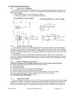
3.5.9. AUX Output Signal
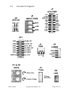
The connection at location JP1 F1,F2 can be used to provide a signal to an amplifier or auxiliary accessory
or slave power supply (like the DSX12V) to come on after the Turn On pulse is sent. This is an open collector
output at F1 and F2 is ground. A relay or transistor is required to deliver a 12 volt output at this location. This
pin should sink no more than 50mA and has an allowable pull-up range of 0-25 volts.