


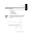


Controls and Connectors
11-22 Monitor Installation and Patient Safety
Monitor Installation
and Patient Safety
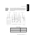
Note—Do not apply a voltage of more than ±12V to any of these outputs.
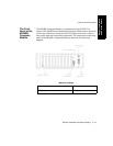
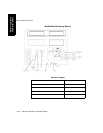
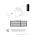
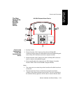
The connectors on the rear panel of the computer module (together with
their connecting function cards) are:
1. System Power Connector; on the M1046A Computer Module, this
is a connector used to input the 60V dc power supply from the
CRT display module. It is not for use on the M1046B Computer
Module but is instead fitted with a stub connector.
2. Equipotential Grounding Terminal; this is used to connect the
computer module to the hospital´s grounding system.
3. Philips monitoring network connectors (Philips Network
Interface); these are Philips monitoring network connectors, used
to input/output information to/from a Philips monitoring network.
4. Human Interface Connector (Utility CPU); this is a Philips HIL
connector, used to input information from the keypad in the
display module.
5. Nurse Paging Relay output; this is a mini-phone jack, used to
connect to the hospital´s Nurse Paging System.
6. Analog Interface Connector; a 37-pin “D” type connector is used to
output information to analog devices.
7. RS232 Connectors (RS232 Interface); these are 25-pin “D” type
connectors, used to output information to printers or computers,
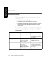
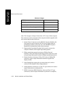
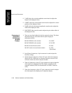
RS232 Connectors
±12 V
HDLC Connector 5 V
Video Out (9) 5 V
Flatscreen Remote Power Supply On/Off 15 V
Video Out (11) 60 V
Maximum Voltages