E‐14HardwareReferenceManual www.picocomputing.com PicoComputing,Inc.
20
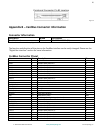
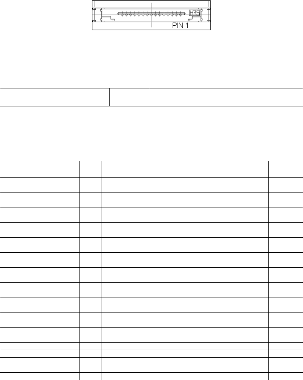
PeripheralConnectorPin#1Location
Figure5
AppendixB
–
CardBusConnectorInformation
ConnectorInformation
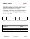
Description Brand PartNumber
CardBusHeader Hirose IC9‐68RD‐0.635SF‐(51)
ThePicoE‐14willmatewithanyType‐IICardBusHeader
ThefunctionanddirectionofthepinsontheCardBusinterfacecanbeeasilychanged.Pleaseseethe
“DigitalBusInterface”sectionformoreinformation.
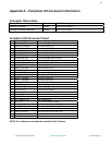
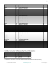
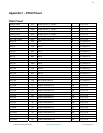
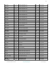
CardBusConnectorPinout
Name Pin Description Dir
GND 1 CardGround PWR
CAD0 2 CardBusData/Address0 IO
CAD1 3 CardBusData/Address1 IO
CAD3 4 CardBusData/Address3 IO
CAD5 5 CardBusData/Address5 IO
CAD7 6 CardBusData/Address7 IO
C\C\/\B\E
\
0
\
7 CommandandByteEnable IO
CAD9 8 CardBusData/Address9 IO
CAD11 9 CardBusData/Address11 IO
CAD12 10 CardBusData/Address12 IO
CAD14 11 CardBusData/Address14 IO
C\C\/\B\E
\
1
\
12 CommandandByteEnable IO
CPAR 13 Parity IO
C\P
\
E\R\R
\
14 ParityError IO
C\G
\
N\
T
\
15 Grand I
C\I
\
N\
T
\
16 CardIntertRequest O
VCC 17 CardPower(3.3V) PWR
VPP 18 CardProgrammingVoltage(NotUsed) PWR
CCLK 19 CardBusClock I
C\I
\
R\D\Y
\
20 InitiatorReady IO
C\C\/\B\E
\
2
\
21 CommandandByteEnable IO
CAD18 22 CardBusData/Address18 IO
CAD20 23 CardBusData/Address20 IO
CAD21 24 CardBusData/Address21 IO
CAD22 25 CardBusData/Address22 IO
CAD23 26 CardBusData/Address23 IO
CAD24 27 CardBusData/Address24 IO
CAD25 28 CardBusData/Address25 IO


