


- 42 -
4.4.4 802.1Q VLAN Setting example
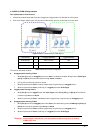
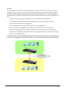
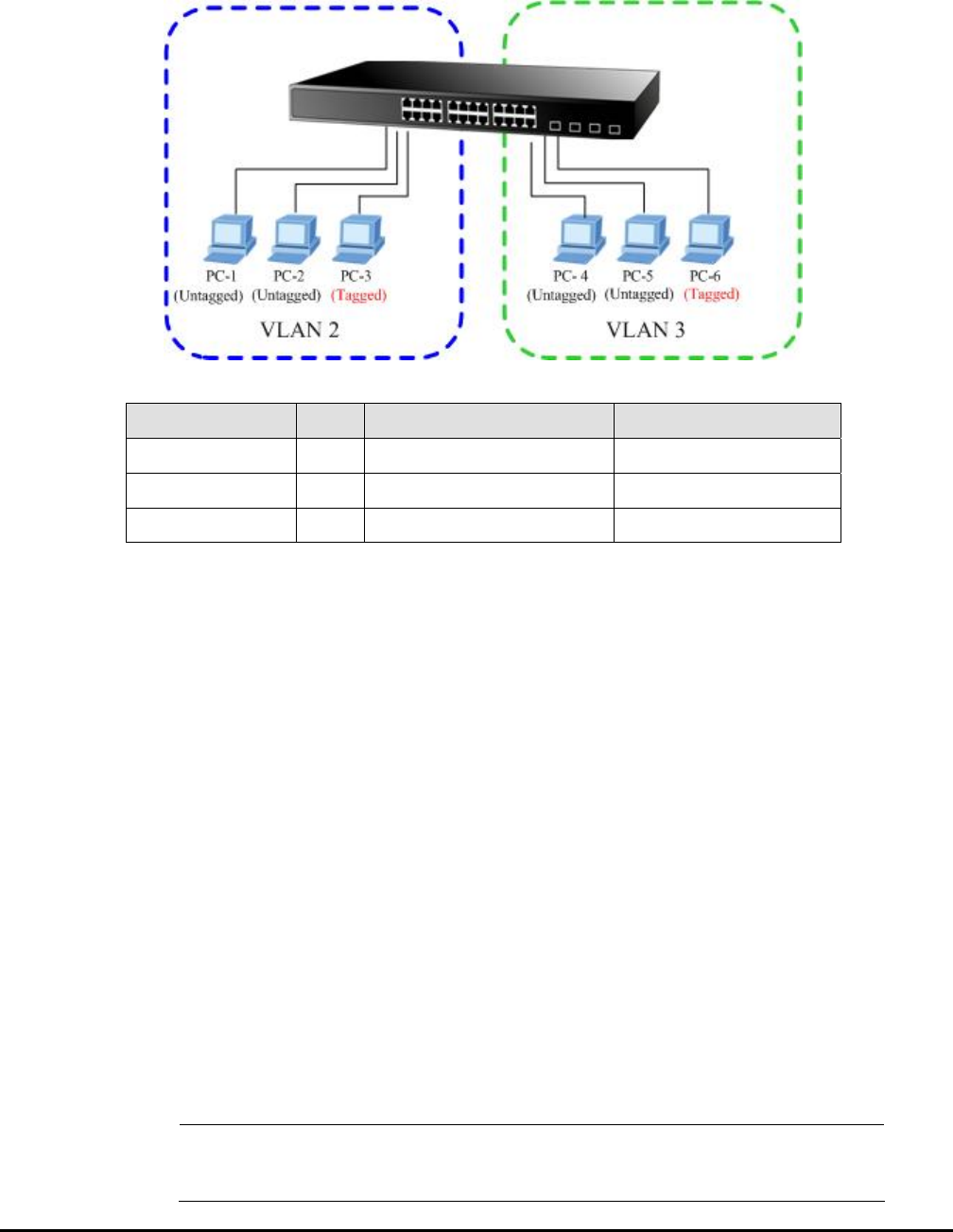
Two separate 802.1Q VLAN scenario
1. Shows how the Web Smart Switch handles Untagged and Tagged traffic from two 802.1Q VLAN groups.
2. Each VLAN isolate network traffic, only the same VLAN member port can receive traffic from each other.
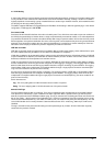
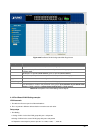
Figure 4-33 two separate 802.1Q VLAN diagram
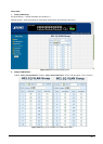
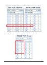
VLAN Group VID Untagged Members Tagged Members
VLAN Group 1 1 Port-7~Port-24 N/A
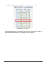
VLAN Group 2 2 Port-1,Port-2 Port-3
VLAN Group 3 3 Port-4,Port-5 Port-6
Table 4-13 VLAN and Port Configuration
The scenario described as follow:
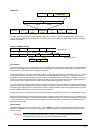
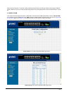
Untagged packet entering VLAN 2
1. While [PC-1] transmit an untagged packet enters Port-1, the Web Smart Switch will tag it with a VLAN Tag=2.
[PC-2] and [PC-3] will received the packet through Port-2 and Port-3.
2. [PC-4], [PC-5] and [PC-6] received no packet.
3. While the packet leaves Port-2, it will be stripped away it tag becoming an untagged packet.
4. While the packet leaves Port-3, it will keep as a tagged packet with VLAN Tag=2.
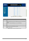
Tagged packet entering VLAN 2
5. While [PC-3] transmit a tagged packet with VLAN Tag=2 enters Port-3, [PC-1] and [PC-2] will received the
packet through Port-1 and Port-2.
6. While the packet leaves Port-1 and Port-2, it will be stripped away it tag becoming an untagged packet.
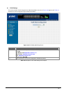
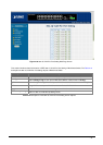
Untagged packet entering VLAN 3
7. While [PC-4] transmit an untagged packet enters Port-4, the switch will tag it with a VLAN Tag=3. [PC-5] and
[PC-6] will received the packet through Port-5 and Port-6.
8. While the packet leaves Port-5, it will be stripped away it tag becoming an untagged packet.
9. While the packet leaves Port-6, it will keep as a tagged packet with VLAN Tag=3.
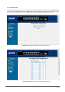
#Notice:
At this example, VLAN Group 1 just set as default VLAN, but only focus on VLAN 2,
VLAN 3 traffic flow.