


Chapter 2 Hardware Installation
Before you proceed with the installation, it is necessary that you have enough information
about the
IP Power Manager
.
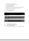
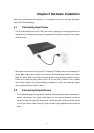
2.1
Connecting Input Power
The
IP Power Manager
h
as an IEC C20 power
inlet for supplying and
managing power for the
output devices. Connect
the power cord to
the power inlet and plug the
other
end into
a
power
outlet as shown:
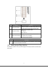
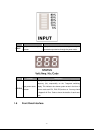
After power connected. You may see the 7-Segment LED display some error messages. If it
shows “E01”, please refer to section 2.6 to connect
IP Power Manager
8000 to your LAN or
WAN. If it shows “E16”, that is mean the power phase of connected power outlet is reverse.
Please try to make the power phase correct. Or you can refer to section 5.2.2 to disable
Input Phase Detection on
IP Power Manager
temporally. For other error message, please
refer to Appendix A Error Code for details.
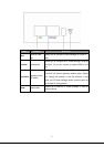
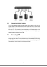
2.2
Connecting Output Device
- 6 -
The
IP Power Manager
has eight power outlets for
connecting devices such as workstations,
servers, and printers. Their power on/off status can be
controlled
manually as well as
remotely through the LAN and
Console
ports. Connect the power
connectors of the
devices
to
each of the power
outlets A through H with the power cords supplied with the devices as
shown: