


WGS3 Layer 3 Switch User’s Manual
- 9 -
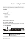
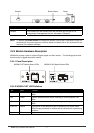
2.4.1 Making a Connection to an RJ-45 Port
The Gigabit copper ports support Auto-MDI/MDI-X. You can use straight-through or crossover
twisted-pair cable to connect any gigabit copper port on the switch to any device that uses a standard
network interface such as a workstation or server, or to a network interconnection device such as a
bridge or router.
Prepare the network devices you wish to network. Make sure you have installed 10BASE-T,
100BASE-TX or 1000BASE-T network interface cards for connecting to the switch's RJ-45 ports.
Prepare straight-through shielded or unshielded twisted-pair cables with RJ-45 plugs at both ends. Use
100-ohm Category 3, 4 or 5 cable for standard 10Mbps Ethernet connections, 100-ohm Category 5 cable
for 100Mbps Fast Ethernet connections, or Category 5e cable for 1000Mbps Gigabit Ethernet
connections.
Connect one end of the cable to the RJ-45 port of the network interface card, and the other end to any
available RJ-45 port on the switch. When inserting an RJ-45 plug, be sure the tab on the plug clicks
into position to ensure that it is properly seated. Using the switch in a stand-alone configuration, you can
network up to 26 end nodes
NOTE: Make sure each twisted-pair cable does not exceed 100 meters (328 feet). We advise using
Category 5e cable for all network connections to avoid any confusion or inconvenience in the
future when you upgrade attached devices to Gigabit Ethernet.
Restrictions on Cascade Length - The IEEE 802.3 standard recommends restricting the number of
hubs (i.e., repeaters) cascaded via twisted-pair cable to 4; while IEEE 802.3u provides even stricter
recommendations for Fast Ethernet. Therefore, when cascading devices other than this switch, please
refer to the accompanying documentation for cascade restrictions. However, note that because switches
break up the path for connected devices into separate collision domains, you should not include the
switch or connected cabling in your calculations for cascade length involving other devices.
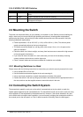
2.4.2 Making a Connection to an Gigabit Fiber Module
The modules are fitted with SC connectors. Please be sure you run cable from the Rx (Tx) port on the
module to the Tx (Rx) port on the target device. The length of Gigabit fiber optic cable for a single
switched link should not exceed 220m for 62.5/125 multimode fiber and 500 m for 50/125 multimode fiber.
However, power budget constraints must also be considered when calculating the maximum cable length
for your specific environment.
2.5 Powering On the Switch
Plug the power cord into the power socket on the rear of the switch, and the other end into a power
outlet.
Check the LED marked PWR on the front panel to see if it is on. The unit will automatically select the
setting that matches the connected input voltage. Therefore, no additional adjustments are necessary
when connecting it to any input voltage within the range marked on the rear panel.
The switch performs a self-diagnostic test upon power-on. (Note that this test takes about one minute to
complete.)