


WGS3 Layer 3 Switch User’s Manual
- 237 -
the OSPF protocol for each area. The Designated Router exchanges routing information with all other
routers in its area, and then floods Link State Advertisements (LSAs) to each router, allowing them to
update their database. This eliminates the need for each router to exchange information with every other
router in its area. The OSPF protocol selects the DR and BDR based on the router with the highest
priority, or highest Router ID in case of a tie.
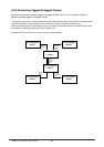
Area Border Router – An Area Border Router (ABR) must be configured between each area and the
backbone. An ABR should be configured with an IP interface that connects directly to both the backbone
and the area on which it borders. However, if an area is not physically connected to the backbone, you
can configure a virtual link that crosses a neighboring area to reach the backbone. Just define an ABR
(i.e., virtual neighbor) on the boundary between the isolated area and transit area, as well as an ABR on
the boundary between the transit area and the backbone. An ABR can be situated between one or more
areas, but we advise limiting the maximum number of areas supported by a single ABR to three. You can
also define a virtual link as a backup path between an ABR and the backbone.
Area Range – An ABR maintains a separate routing table for each area to which it is attached, and
sends routing summaries for each attached area to the backbone, which in turn distributes this
information to other areas in the autonomous system. This reduces the size of the routing tables that
have to maintained throughout the system, and prevents frequent updates from flooding the system
whenever a link change occurs. To configure a routing summary, you must define the OSPF Area Range
for all the networks within an ABR’s area. This range is specified with an IP address and network mask
(page 2-60 or 3-45). Moreover, since OSPF supports Variable Length Subnet Masks (VLSMs), you can
specify a mask on a bit boundary, which can further reduce the number of advertised addresses.
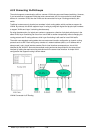
Autonomous System Boundary Router – An Autonomous System (AS) contains all the routers in your
network, each of which shares information with other routers to determine a shortest-path route to every
destination in the AS. However, when an AS is connected to an outside network, it must import external
routing information through an Autonomous System Boundary Router (ASBR). An ASBR can import
routing information through other routing protocols such as RIP.
An ASBR will generate external link advertisements on selected interfaces if OSPF is enabled globally,
and any of the following conditions exist on an interface:
• RIP is enabled, or
• RIP and OSPF are both disabled.
Link State Advertisements – Each router maintains a link state database that contains information
received from all the other routers within the same area. There are four types of Link State
Advertisements (LSA). Router LSAs advertise area links known by the originator, and are issued by all
routers. Network LSAs advertise transit areas through which traffic can be passed to reach other areas in
the system. Network LSAs contain information about all the routers that provide a link across the transit
area, and are issued by Designated Routers.
Summary LSAs are issued by Area Border Routers (ABR), and advertise routing information for a single
subnetwork outside the ABR’s area or for an Autonomous System Boundary Router (ASBR). External
LSAs are issued by the ASBR, and contain information about external networks outside the AS.
Virtual Links – All areas within an Autonomous System must connect to the backbone. In cases where an
area cannot be physically connected to the backbone, you can create a virtual link which crosses a
transit area to reach the backbone.
(Virtual links can only span one intermediate area to reach the backbone.) Virtual links can be used as a
redundant link, preventing partitioning from the backbone. They can also be used to merge two separate
backbone areas.