


Part 12
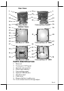
backpack into the cable cover area of main unit.
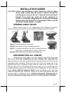
The area required for wall mount application is determined by the
main unit dimensions and is 376 mm in width and 315 mm in height.
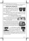
BASE MOUNT UPGRADE KIT
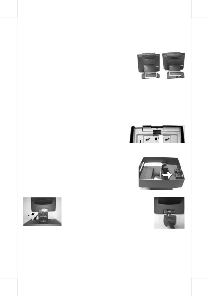
On rear edge of the stand assembly for
desktop mount application, there is a rear connect
cover. Either a 2nd LCD display panel option LM-
6201 or LM-6301 or a customer display option PD-
2501 or PD-2602 or PD-305 can be installed here
after removing this cover.
Please note that there could be certain restrictions to the tilt angle
range for the main unit when the base mount upgrade kit is mounted.
Investigation for the acceptability of such kind of restrictions must be taken
before decision to install a base mount upgrade kit.
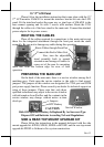
12” 2
nd
LCD Panel Or Customer Display
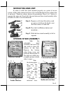
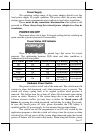
To remove the rear connect cover in slim base please refer to the
inside view of the base unit after removal of UPS
battery as in picture at right and use a flat head
screwdriver to pick the plastic hook plate of the
rear connect cover from inside.
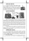
The rear connect cover of universal base can be removed by pushing
the plastic hook plate of it from inside as marked by
white arrow in the right picture. However, this picture
is a top-side-down inside view of the stand assembly
with base box removed for illustration purpose only.
Please push the plastic hook plate with finger through
the top opening in the stand assembly to remove the
rear connect cover.
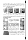
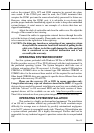
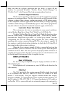
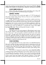
Fit the joint base of PD-2501
or PD-2602 or PD-305 or LM-6201 to
the rear connect cover opening. Then
make the cable go through the normal
cable exit (under the joint base) as in
these pictures. Fit 2 screws with
washers to hold the joint tight. For low profile customer display PD-305, the
installation procedure is same. Remember to enable the +5 V DC supply in the
COM port of the main unit for PD-2501, PD-2602 or PD-305 or the +12 V DC
in VGA port for LM-6201.