


Part 13
15” 2
nd
LCD Panel
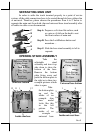
Please follow the installation instruction that come alone with the 15”
2
nd
LCD monitor LM-6301 to mount the interface bracket kit onto the LCD
panel. Fit the interface bracket the same way as joint base of LM-6201 to the
rear connect opening and fix with 2 screws with washers. Route the VGA
through the cable exit of the base stand to the main unit. Connect the attached
power adaptor for its power source.
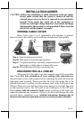
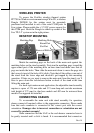
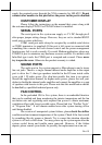
ROUTING THE CABLES
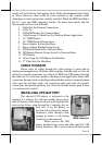
Place all the cables required for connections to the main unit except
those for the integrated attachment through the front part inside the stand
assembly. Be sure not to damage any cable during this operation.
Now, turn the adjustable
stand assembly back to normal
orientation and arrange all cables to
come out of the area for mounting
main unit from the bottom edge for ease of later
operation.
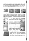
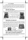
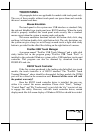
PREPARING THE MAIN UNIT
On the back of the main unit, there is a service window among the 4
matching pegs. Push open the service window to the right to find several
jumpers. The jumpers in this window are designated for VGA port and COM
port power supply function. Please consult your dealer for technical support on
setup of these jumpers. Please note that only those
qualified technicians may adjust in the service window
with information from Posiflex and the contents in the
service window may change without notice as time
develops.
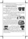
SIDE & REAR TOP MOUNT UPGRADE KIT
Please follow the instructions in the manuals delivered with the side
mount upgrade kit: KP100, SD100, SD200 or BC100U and the rear top mount
upgrade kit PD302 to fit them in Jiva system construction.
Route Cables through Front Part
Connect this End to Main Unit
Service Window
Jumpers
CAUTION
Risk Of Explosion If Battery Is Replaced By An Incorrect Type
Dispose Of Used Batteries According To Local Regulations
RTC Battery