


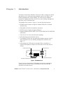
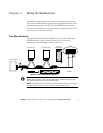

WIRING THE MODBUS CARD
EATON Powerware
®
Modbus
®
Card User’s Guide S 164201376 Rev C www.powerware.com
8
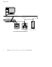
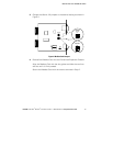
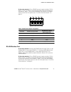
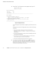
Four-Wire Networks
The Modbus Card also supports four-wire, half-duplex, RS-485 networks.
Figure 7 shows a detailed view of four-wire connections using the
Modbus Card terminal strip.
Slave Device #1
Master Device
Slave Device #2
*See Note
R
T
*
R
T
*
R
T
*
R
T
*
UPS with
Modbus Card
RxD+ RxD–TxD+ TxD–
T--R+ T+Gnd R-- T--R+ T+Gnd R--
T--
R+
T+
Gnd
R--
Figure 7. Four-Wire RS-485 Modbus Network
NOTE Belden 9842 or equivalent cabling (a dual twisted-pair shielded cable with ground)
is recommended.
NOTE If the Modbus Card is the last device installed in the network chain or the length of
the network cable is excessive, termination needs to be enabled (see page 10).
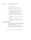
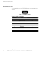
RS-485 Terminal Strip
The RS-485 five -position terminal strip provides an alternate interface to
attach the RS-485 transmission lines. This connector also allows external
resistors to be applied to terminate the network.
Before connecting the RS-485 network to the Modbus Card, remove the
detachable plug from the 5-pin terminal strip connector. The RS-485
signal names are shown just above the connector (see Figure 8).
For two-wire networks. Connect the RS-485 network signal TxD(+) to the
RxD(+) input signal on the Modbus Card terminal strip. Connect the
RS-485 network signal TxD(–) to the RxD(–) input signal on the Modbus
Card terminal strip. The Modbus Card factory-default jumper setting for
J9 and J10 is two-wire communication.