


WIRING THE MODBUS CARD
EATON Powerware
®
Modbus
®
Card User’s Guide S 164201376 Rev C www.powerware.com
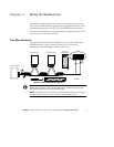
11
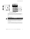
1
J11
S2
J7 J8
J10
J9
RxD(–) Pull Down (620Ω)
RxD Terminator (120Ω)
Four-Wire
Two-Wire
ON
*OFF
123456
TxD(–) Pull Down (620Ω)
TxD(+) Pull Up (620Ω)
TxD Terminator (120Ω)
RxD(+) Pull Up (620Ω)
*Factory-default = OFF
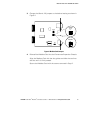
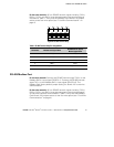
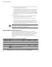
Figure 10. S2 Termination Configuration
If a value other than the on-board 120 ohm termination is required, then
S2-3 and S2-4 should be set to the OFF position. The Modbus Card
terminal strip provides easy access to attach external termination
resistors across the TxD(+), TxD(–), RxD(+), and RxD(–) RS-485 network
lines.
Biasing Resistors
CAUTION
Biasing resistors should be used at only one point in the RS-485 network.
Biasing resistors are used to ensure that the idle voltage sensed across
the receiver does not create false data bits. The factory-default for
S2 (1–6) is OFF.
Two on-board 620 ohm biasing resistors may be selected by setting
S2-1 and S2-2 to the ON position. If biasing is set at the master terminal
unit, then S2-1, S2-2, S2-5, and S2-6 should be set to the OFF position.