


WIRING THE MODBUS CARD
EATON Powerware
®
Modbus
®
Card User’s Guide S 164201376 Rev C www.powerware.com
10
3
8
7
9
1
6
245
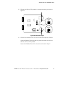
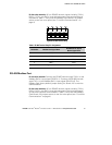
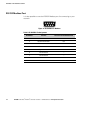
Figure 9. RS-485 DB-9 Pin Numbers
Table 2. RS-485 DB-9 Pin Assignments
Pin Number Modbus Card Signal Name
RS-485 Network Signals
Master Signal Name
1 RxD(+) TxD(+)
2 TxD(+) RxD(+)
3 Signal common Signal common
4 Reserved —
5 Reserved —
6 RxD(–) TxD(–)
7 TxD(–) RxD(–)
8 Reserved —
9 Reserved —
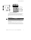
Termination
CAUTION
Termination resistors should be placed only at the extreme ends of the RS-485 network. No
more than two termination points should be used in the RS-485 network.
Termination is not required unless the Modbus Card is located at the
end of the RS-485 network or the length of the network cable is
excessive.
If receive termination is required, an on-board 120 ohm termination
resistor may be selected by setting S2-3 to the ON position. A 120 ohm
resistor will be placed in parallel with the RxD(+) and RxD(–) lines (see
Figure 10).
If transmit termination (four-wire networks) is required, an on-board
120 ohm termination resistor may be selected by setting S2-4 to the ON
position. A 120 ohm resistor will be placed in parallel with the TxD(+)
and TxD(–) lines (see Figure 10).