


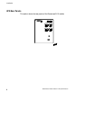


Additional UPS Features
14
Powerware
®
5115 User’s Guide : www.powerware.com
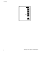
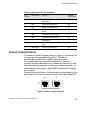
Table 1. DIP Switch Settings
120V Models
Output Voltage Input Voltage Range DIPSwitch1 DIPSwitch2
110V 99V-116V ON OFF/ON
120V* 108V–127V* OFF OFF/ON
230V Models
Output Voltage Input Voltage Range DIPSwitch1 DIPSwitch2
220V 198V–233V ON OFF
230V* 207V–243V* OFF OFF/ON
240V 216V–254V ON ON
*Default position
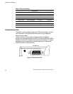
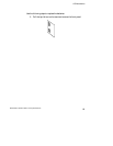
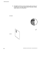
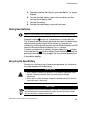
Communication Port
To establish communication between the UPS and a computer, connect
your computer to the UPS communication port using the supplied
communication cable.
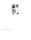
When the communication cable is installed, power management
software can exchange data with the UPS. The software polls the UPS for
detailed information on the status of the power environment. If a power
emergency occurs, the software initiates the saving of all data and an
orderly shutdown of the equipment.
3
8
7
9
1
6
245
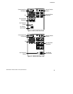
UPS Rear Panel
Figure 13. Communication Port