


Installation
9
Powerware
®
5119 User’s Guide www.powerware.com
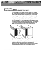
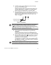
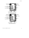
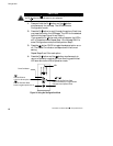
Communication Port
Battery Connector
Load Segment 1
(Three IEC-320 Receptacles)
Load Segment 2
(Three IEC-320 Receptacles)
10A, IEC-320
Input Connector
Option Slot
Input Circuit Breaker
Network
Transient Protector
Load Segment 3
(Three IEC-320 Receptacles)
Figure 8. 2000-2400 VA, 230V Rear Panel
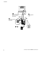
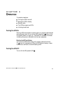
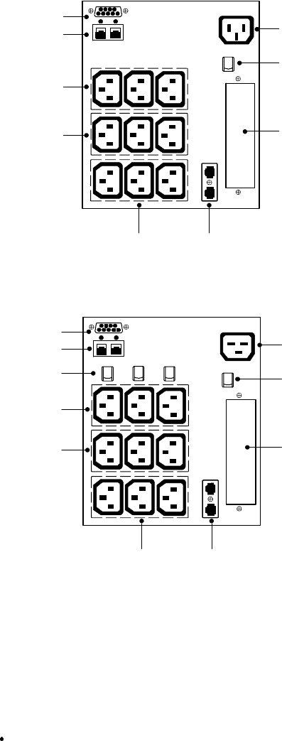
Communication Port
Battery Connector
Load Segment 1
(Three IEC-320 Receptacles)
Load Segment 2
(Three IEC-320 Receptacles)
Output Circuit Breakers
16A, IEC-320
Input Connector
Option Slot
Input Circuit Breaker
Network
Transient Protector
Load Segment 3
(Three IEC-320 Receptacles)
Figure 9. 3000 VA, 230V Rear Panel