


Additional UPS Features
27
Powerware
®
5119 User’s Guide www.powerware.com
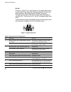
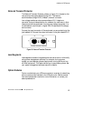
Network Transient Protector
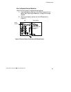
The Network Transient Protector, shown in Figure 18, is located on the
rear panel and has jacks labeled IN and OUT. This feature
accommodates a single RJ-45 (10BaseT) network connector.
Low voltage models can also accommodate an RJ-11 telephone
connector that provides protection for modems, fax machines, or other
telecommunications equipment. As with most modem equipment, it is
not advisable to use this jack in digital PBX (Private Branch Exchange)
environments.
Connect the input connector of the equipment you are protecting to the
jack labeled IN. Connect the output connector to the jack labeled OUT.
IN OUT
OUT
IN
NETWORK TRANSIENT PROTECTOR
Figure 18. Network Transient Protector
Load Segments
Load segments are sets of receptacles that can be turned on individually
using power management software. For example, during a power
outage, you can keep key pieces of equipment running while you turn
off other equipment. This feature allows you to save battery power. See
your power management software manual for details.
Option Modules
Option modules help your UPS communicate in a variety of networking
environments and are installed in the UPS option slot. See the manual
that accompanies each module for more information, or contact your
sales representative.