


Installation
18
Powerware
®
5125 Tower (1000–2200 VA)User’sGuide RevB www.powerware.com
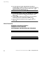
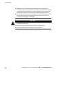
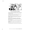
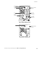
UPS Battery
Connector
EBM CableEBM Battery Connector
Output Receptacles
Communication Port
Power Cord
Figure 2. Typical Installation with Two EBMs
4. If you are installing power management software, connect your
computer to the UPS communication port using the supplied
communication cable.
5. On 208V/230V models, plug the detachable UPS power cord
into the input connector on the UPS rear panel.
6. Plug the UPS power cord into a power outlet. The front panel
indicators cycle through a startup sequence while the UPS
conducts a self-test.
When the self-test is complete, the
indicator flashes,
indicating the UPS is in Standby mode with the equipment
offline. If the alarm beeps or a UPS alarm indicator stays on, see
Table 9 on page 44.
7. Plug the equipment to be protected into the appropriate UPS
output receptacles (see page 32 for more information on load
segments).
DO NOT protect laser printers with the UPS because of the
exceptionally high power requirements of the heating elements.