


25
Powerware
®
5125 Tower (1000–2200 VA)User’sGuide RevB www.powerware.com
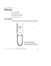
CHAPTER 4
OPERATION
This section describes:
Operating modes
Turning the UPS on and off
Starting the UPS on battery
Initiating the self-test
Operating Modes
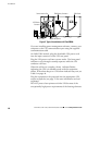
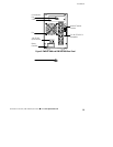
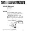
Powerware 5125’s front panel indicates the UPS status through the UPS
indicators. Figure 11 shows the UPS front panel indicators and controls.
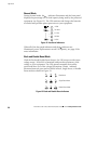
Normal Mode Indicator (Solid Green)
Standby Mode Indicator (Flashing Green)
Buck Mode Indicator (Solid Green, Solid Red)
Boost 1 Mode Indicator (Solid Green, Flashing Red)
Boost 2 Mode Indicator (Flashing Green, Solid Red)
Red